Stilgar's 3D printer build

stilgarhammer

New Member
I have been poked into doing a build thread of my current project of a 3D printer. So here goes.

I am a member of the reprap forum. http://reprap.org/. What is a reprap?

RepRap is humanity's first general-purpose self-replicating manufacturing machine.

RepRap takes the form of a free desktop 3D printer capable of printing plastic objects. Since many parts of RepRap are made from plastic and RepRap prints those parts, RepRap self-replicates by making a kit of itself - a kit that anyone can assemble given time and materials. It also means that - if you've got a RepRap - you can print lots of useful stuff, and you can print another RepRap for a friend...

RepRap was the first of the low-cost 3D printers, and the RepRap Project started the open-source 3D printer revolution. It has become the most widely-used 3D printer among the global members of the Maker Community.

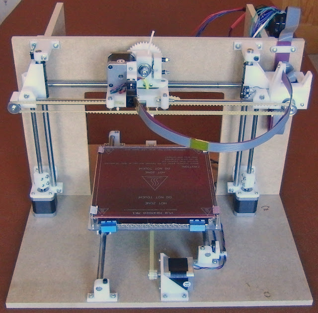
Now to my project.. After much research and thought I found I like the design of the Mendel90, a design by Nophead that replaces many of the threaded rods and printed parts of the Prusa Mendel with flat sheets of MDF, Dibond, Acrylic or any other stiff sheet material. This simplifies construction, stiffens the frame, and always keeps the axes at 90 degree angles, hence the name. It is also the most customizable of the printers. By upsizing many of the parts, any size printer can be made.

Here is the mendel90 as built by Nophead, the gray panels are MDF wood.
M90.JPG


My printer will be made of acrylic painted in green with white plastic parts.

Progress as of 3/18/15,
I have the base plate drilled for the mounting points. and ready for paint.

Next on the list to to build and install the Y axis ( the red bed looking thing, and the motor in center front in the above pic).
 

Rhaven Blaack

!!!THE MAN BEHIND THE CURTAIN!!!
Staff member
Administrator
Moderator
This is interesting!
I am looking forward to seeing your developed.
I wish you the best of luck with it!!!thumbsup
 

zathros

*****SENIOR ADMINISTRATOR*****
Staff member
Administrator
Moderator
Very nice. The machine pictured should have gussets on both sides though as it could still warp in the middle, on the bottom plate.. It's odd how it has the one side stiffened and not the other.

Do you own a welder? You could come up with such a better design. these machines are temporary. The MDF will absorb moisture eventually. The parts are not very strong, and will make this design vibrate. Run slowly, this won't be a problem. I programmed CNC machines, up to 8 axis, for quite sometime. Some of these were the size of small houses. Vibration if always a problem. If the threaded rods are not purpose made, i.e., for milling machines/lathes, or grinders, and do not have a double nut set up so there is zero backlash, then will not be accurate. Some, that use ball bearings, and cages are quite excellent, but all must have a method of taking up backlash. The problem with steel rods in holes is that the plastic holes will eventually elongate and there will be no way of tightening them up.

I've worked on Milling machines 40 years old, worked continuously, with the table still having only .0005" movement from side to side. These machines bleed oil all the time, and it is recycled, and used again and again to reduce friction to almost nothing.

The machines I programmed were high speed milling machines, with a table large enough to put a full size Van on. The screws were 3" in diameter. It was the double nut back lash system that kept backlash at virtually "0".

I plant on using 3/8ths thick flat T6061 when I built one, for the table, and a purpose built welded frame out of much heavier steel. I have a small milling machine I may convert instead, then I could do CNC milling, and attach a head to the spindle, to do 3D printing. For the effort it takes to make these machines, the design above will yield results not much better than a MakerBot., the aforementioned reasons being stated.

My son is working with this at our local high school, it cost $1375. Unless you make a substantially bigger machine, it isn't worth making one. The cost difference between scaling up isn't much either, when making your own machine, you are using the same components, just longer rods, and longer belts. The reason I ask if you had a welder is that being able to weld a solid frame, that could be screwed down to either a cement block, or cement/steel, pedestal, screwed down, you could end up with a much stronger, long term machine, and the table would be the only major expensive, as you would be using a piece of aluminum of steel. The rest could be made of scrap steel. I make many things out of scrap steel.

The more rigid and vibration free, the better the ability to do prototyping, i.e., mold plugs for investment casting. I find the finish on most of these machines having trouble with the final finish. Many could be be polished smooth. Making one of these machines could hit the $1375 dollar mark rather quickly. I guess what I am trying to say is built the biggest machine you can. It is an economy of scale. You will have better results as the bigger machine will be inherently stronger, as long as it is scaled up properly, taking material strengths and weaknesses into account. I think the rod system will work fine, it is is continuously lubricated. I have seen so many of these machines run dry, and they vibrate more and more, and the finish only gets worse.

Thanks for starting this thread. :)

hero-truck.png
 

stilgarhammer

New Member
The pic is of the prototype he built. There has been several updates since it was made. Here is a update on my project.
Here is my acrylic 1/4" thick base-plate. with a Bright Aqua metallic paint (DSGM440). Here I am test fitting the plastic parts to the base-plate. The motor is at the front. I still have the aluminium channel that goes under the base-plate, front to back. There is 4 white rubber feet on bottom to help with noise. I am building this machine for my hobby and don't need large or perfect prints.

IMG_20150320_183558_zpsqz59ione.jpg
 
Last edited:

zathros

*****SENIOR ADMINISTRATOR*****
Staff member
Administrator
Moderator
This looks like it's going to be a big one. What is the workspace you predict? I don't know what your experience is in machine tooling/fabrication/set up. The main problem with these machines is vibration. Those rubber feet may reduce the noise, but the plastic does not "know" they are there and will react to the vibration, and will severely affect the outcome. I was working with a version of these printers that was classified in 1983. The technology is actually old, there are many forms that these printers take shape. It's just that it is being released to the masses now. Vibration is the enemy, rigidity is your friend, noise, is the vibration escaping. Quieting down the noise turns the sound waves into mechanical energy. Thus, the rubber feet keep the vibration on the machine, and it will buzz ever time the stepper motors move. The idea is to transfer the vibration and let it takes it's final form in whatever manner it needs, so long as the machine is not vibrating. :)
 
Last edited:

stilgarhammer

New Member
The base in about 18 inch square. The working area on the heat-bed is 7 1/2 inches square by about 7 inches tall. I have experience with several milling and cnc machines in the injection mold field. I also have a technician classification for industrial robotics ( programming and assembly). I know about the vibration and at times its vary bad. The rubber feet is to keep the noise on the machine and not the wood table it will be on. I have rubber dampers for the stepper motors (not shown on the base motor in the last pic), As stated in last post this is only a test fit and the wiring has yet to be made to the stepper motor and limit switch. When I get the wires together for the motor I will install the damper. I will be preliminary testing each axis at a time for vibration and stickiness.
 

zathros

*****SENIOR ADMINISTRATOR*****
Staff member
Administrator
Moderator
The lube will really be crucial. That's good to know you have the knowledge you do. It will make commenting easier. You never know what people have done or know and don't want to be insult by accident. With that size envelope, you could make some pretty intense stuff. Think how many parts that could add up too! Last CNC machine I programmed had 15 h.p. on each axis(4), initial set up was a real drag, loading the collets through the spindle. I started loading them in the pockets in the back which hey didn't like. I guess they thought someone might not see me back there. My attitude was "don't touch my machine on my shift!".

You know, if you were so inclined to make up a parts list, the could really be a "Bible" of sorts for those getting started out. This thread will attract views. Do you plan to do any YouTube videos? They can be embedded here. This is really prototyping, and is great to watch the creative process. One of the places I worked was using the liquid 3D resin printers with the Laser Beams for fast prototyping. Back then, there was no training for this except by the company you worked for, and it was all classified, so you could never talk about it. It made for very odd job interviews. :)
 

stilgarhammer

New Member
There is alot of info and videos out there. I will post some links that I use. I should point out that there is two versions of the mendel90, The first is the one I am doing here with the acrylic sheets, and the second uses the MDF sheets. The big difference between the two that I have found is, other than the sheet material, is that the second version uses updated plastic parts and is called sturdy. In the build videos link below he is building the sturdy version. The video with the black is using a material called Dibond (It is comprised of two pre-painted sheets of .012" aluminum with a solid polyethylene core), is a kit that you can get from the designer in the UK.

This is the section on the mendel90 on the reprap.org. http://reprap.org/wiki/Mendel90
Here is the build manual, it a bit vague, but its the best I have found so far. http://reprap.org/wiki/Mendel90_Build_Manual

Here are the video links

designer's pages
https://github.com/nophead/Mendel90
http://hydraraptor.blogspot.com/2011/12/mendel90.html
To order kits. http://forums.reprap.org/read.php?94,196585

Sorry about posting links and not embedding, I found on some browsers the embedded videos have trouble running.
zathros, yes, I do have experiance making web pages as well.
 

zathros

*****SENIOR ADMINISTRATOR*****
Staff member
Administrator
Moderator
It's really great when we have someone who is so knowledgeable join the forum. I have no pride, in the sense of being corrected, I love to learn. I have aluminum sheets with Nomex Honeycomb (type) material between them, and it is so strong, around .0625", I use it as a floor piece in my kitchen that is an inside hatch to my basement. My house is very old. It has three ways of getting into the basement and they all suck! The floor piece is light enough so on those cold nasty days, I go into the basement, where all my laundry machines, furnace, etc. is, and I don't have to leave the house.

Materials knowledge is a great thing. I obviously am not a "paper purist" when it comes to making models. I like the endeavor, the friendships, and associations that come from the hobby.

Personally, I would go acrylic over MDF. I don't like that material. I have made speakers using it, and I did not like it's acoustic properties. So I went back to wood. I banged out a nice set of tapered 1/4 wave tubes a few years back with an Fs of 29 Hz. They sound great. I may get into speaker building. I have made a few sets of electrostatic speakers too. Those a very labor intensive, and I needed too much space for the jig I made for lining up the mylar sheets. Anyways, I'm rambling.

I have seen many videos on You tube, but seeing one come together, like you are doing, just seems easier to observe, and you make us feel involved in some way. ;)
 

stilgarhammer

New Member
A bit more of a update. Still in the test fitting stage, but getting there. The 12 ounce can is for size refrance.

IMG_20150324_143321_zpsunhjorrx.jpg


For those that want to make a simular 3D printer to this, and don't want to purchase a kit.
I will give you a heads up when sourcing parts here in the USA...

There are two versions of the Mendel90, first vesion (Shown here), uses one set of parts. The second version called "STURDY", uses updated parts, and you will find that most information, videos, and instructions are for the sturdy version.

1. All measurements are in metric. (designer lives in UK)
2. The acrylic sheets and plate class from your local glass dealer. (I ran into a problem because the dealer near me has never used metric measure.)
3. Most (if not all) screws and nuts can be found at FASTENAL, (FASTENAL.com, also has local stores).
4. Use chrome plated steel rods, Mine are 8mm, will last longes. DO NOT USE DRILL ROD it WILL damage linear bearings), Found on Ebay.
5. Printed plastic parts kit, Found on Ebay.
6. All threaded rod, Mine are 8mm, Found on Ebay.
7. PSU, Min 480 watts, Found on Ebay.
8. Nema 17 stepper motors, five required, Found on Ebay.
9. Bearings, two sizes ball, one linear, Found on Ebay.
10. T5 Toothed belt and pulleys, Found on Ebay.
11. J-head Hot end, 1.75mm with a .4mm nozzle, with Cartridge heater and thermister, Found on Ebay.
12. 1.75mm printer filament, Found on Ebay.
13. 214mm heat-bed with thermister, Found on Ebay.
14. fans, 60mm and 80mm , Found on Ebay.
15 controller, Mega 2560 & RAMPS 1.4 & 5 A4988 Stepper Motor Drivers, Found on Ebay.
16. limit leaf switches, min three, Found on Ebay.
17. Springs, 10mm for extruder, 25mm for heat-bed, Found on Ebay.
18. Hobbed bolt for wade extruder, Found on Ebay.
19. LCD & SD card, Found on Ebay.
20. Hookup wire, PSU load resistor, Found on Ebay.

My estamate of cost, around $600US.

Special notes..
The drill guides have to be printed on several sheeps of paper and taped together. Unless you have access to a large printer or plotter. Before drilling double check hole pacement, mistakes are hard to fix in acrylic.

When inserting locknuts in parts, most will need to be heated with a grill lighter (Careful not to melt the insert).
 

stilgarhammer

New Member
Not much to look at at the moment. And I think my electronics is fried. I connect everything as to manufacture and turned on PSU and poof smoke.
I have ordered a new system, that combines all the boards and is warranty.
IMG_20150328_151824_zps0frrzqet.jpg
 
Last edited:

zathros

*****SENIOR ADMINISTRATOR*****
Staff member
Administrator
Moderator
That looks excellent. It would be fine for what you are doing.There are lots of places where you could brace it if you found out you needed too. It's looking great. :)
 
Top