- Apr 5, 2013
- 13,876
- 10,214
- 228
Hopefully this works out. I did tutorial yesterday, but the pictures kept changing location and it made no sense. Here we go again! ")
A New Haven Sharpie. This is the file I will be working with.

My screen and Grid is set up as follows. It doesn't really matter though:

In the Command Line type PictureFrame, then navigate over to the picture of the New Haven Sharpie you downloaded. Make a folder and keep all the info for this model in it, very important!
Type 0,0 (these are numbers, not letters!) for the first corner of the picture to locate at the center in the "Front Viewport". Type 5 (which will be 5 feet) and when the box goes out that direction, just left click at that spot and the picture will appear.
Make copies of the Picture you just inserted. Click on the picture, under Transform, Click on "Copy", and make 2 copies, right click when you are finished to stop copy process. Right click is the same as "Enter".
Double Click the "Front" Viewport, as we will be working there now.
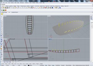
It should look like this:

We are going to loft the Hull. Click the picture once. On the Top Row, you will see many pictures of different functions, click the one that looks like a "Padlock". This will lock the "Pictureframe" in place and allow you to draw on it without moving it.
For now, we will be working with the part that looks like the boat bulkheads, the right side is the front, the left side is the rear. You will use (in this case) Polyline. It is the 3rd selection down from the top on the right. Hold you cursor over it, and it will read "Polyline". Click it once.
Turn "Ortho" on (Ortho stands for Orthogonic, keeps things nice and square), it is BOLD, it is on. Draw a straight line going right up the center of that big fat line, this will be the center of you keel line. For the rest of the lines, you will draw on the outside edge.
It will look like this (do not be afraid to make the picture bigger or smaller to suit your needs:
Now, turn "Ortho" "OFF", select "Polyline. You are going to copy each line of the Hull Loft Lines. Stay to the outside. The point is you stay on the in or the outside, you do not interchange. Trust me on this, stay on the outside.
Click Osnap, and Tick the box that reads "Near", that will start your line on the center of the keel. The last line will start where the bottom of the boat intersects the center keel line, Click and start line there, and run it up try to keep the lengths the same on the sides, (this is the first, or "Default" layer, AFTER YOU HIGHLIGHT IT, GO TO THE RIGHT SIDE OF YOUR SCREEN AND CLICK "PROPERTIES, select "Display Color"/ "Red", so you can se the lines easier.see pic:

Now, do the same for the left side (the rear of the boat). Do NOT connect the lines front side to the rear side of the boat!!
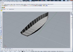
When you are done, draw a box around them, highlighting them all, the click on "Match"under all the details on the right hand side. Click O.K. on the dialog box and all the lines will be red. It should look like this:

"Group" (Located on the left side, three Ball Together" Hover cursor over, it will read "Group" and "Group" "Front" side of the boat" , to de-select an item, just hold down CTRL, and "Left Click", we are going to Mirror them, then Join them.
Select Transform ", Osnap has "Near" Ticked", then select "Mirror", "Start of Mirror Plane will be the Keel Line", move you mouse down or up and you will see the lines appear "Mirrored" on the other side, left click and they will stay there.
Now, Press "Ungroup" for each side. You will now join each one individually. If they did not line up exactly, no problem, Rhino will ask you if you wish to connect the two pieces, you will select yes. Rhino will add the missing piece.
Now, "Group" the pieces you have just joined. Once "Grouped", "Lock them" by pressing the "PADLOCK" button.
You screen should now only show the lines on the left:

I want to check that this is loading properly
A New Haven Sharpie. This is the file I will be working with.
My screen and Grid is set up as follows. It doesn't really matter though:
In the Command Line type PictureFrame, then navigate over to the picture of the New Haven Sharpie you downloaded. Make a folder and keep all the info for this model in it, very important!
Type 0,0 (these are numbers, not letters!) for the first corner of the picture to locate at the center in the "Front Viewport". Type 5 (which will be 5 feet) and when the box goes out that direction, just left click at that spot and the picture will appear.
Make copies of the Picture you just inserted. Click on the picture, under Transform, Click on "Copy", and make 2 copies, right click when you are finished to stop copy process. Right click is the same as "Enter".
Double Click the "Front" Viewport, as we will be working there now.
It should look like this:
We are going to loft the Hull. Click the picture once. On the Top Row, you will see many pictures of different functions, click the one that looks like a "Padlock". This will lock the "Pictureframe" in place and allow you to draw on it without moving it.
For now, we will be working with the part that looks like the boat bulkheads, the right side is the front, the left side is the rear. You will use (in this case) Polyline. It is the 3rd selection down from the top on the right. Hold you cursor over it, and it will read "Polyline". Click it once.
Turn "Ortho" on (Ortho stands for Orthogonic, keeps things nice and square), it is BOLD, it is on. Draw a straight line going right up the center of that big fat line, this will be the center of you keel line. For the rest of the lines, you will draw on the outside edge.
It will look like this (do not be afraid to make the picture bigger or smaller to suit your needs:
Now, turn "Ortho" "OFF", select "Polyline. You are going to copy each line of the Hull Loft Lines. Stay to the outside. The point is you stay on the in or the outside, you do not interchange. Trust me on this, stay on the outside.
Click Osnap, and Tick the box that reads "Near", that will start your line on the center of the keel. The last line will start where the bottom of the boat intersects the center keel line, Click and start line there, and run it up try to keep the lengths the same on the sides, (this is the first, or "Default" layer, AFTER YOU HIGHLIGHT IT, GO TO THE RIGHT SIDE OF YOUR SCREEN AND CLICK "PROPERTIES, select "Display Color"/ "Red", so you can se the lines easier.see pic:
Now, do the same for the left side (the rear of the boat). Do NOT connect the lines front side to the rear side of the boat!!
When you are done, draw a box around them, highlighting them all, the click on "Match"under all the details on the right hand side. Click O.K. on the dialog box and all the lines will be red. It should look like this:
"Group" (Located on the left side, three Ball Together" Hover cursor over, it will read "Group" and "Group" "Front" side of the boat" , to de-select an item, just hold down CTRL, and "Left Click", we are going to Mirror them, then Join them.
Select Transform ", Osnap has "Near" Ticked", then select "Mirror", "Start of Mirror Plane will be the Keel Line", move you mouse down or up and you will see the lines appear "Mirrored" on the other side, left click and they will stay there.
Now, Press "Ungroup" for each side. You will now join each one individually. If they did not line up exactly, no problem, Rhino will ask you if you wish to connect the two pieces, you will select yes. Rhino will add the missing piece.
Now, "Group" the pieces you have just joined. Once "Grouped", "Lock them" by pressing the "PADLOCK" button.
You screen should now only show the lines on the left:
I want to check that this is loading properly