

The foam is stable and very strong (it has a honeycomb nature to it - the self-skinning nature of the material results in a poroduct with a continuous film coating on the top and bottom, with the cellular structure inside), and has a lot of advantages as far as carvability, easy mounting of trees and poles, etc. If you want to make the modules themselves strong enough for lots of travel, are worried about warpage, and don't mind spending a little more than typical wood construction, why not go with foam and aluminum framing? A foam module framed with extruded 6061 aluminum 2"x2" angle bar with TIG welded corners, and maybe a flatbar diagonal for shear strength, wouldn't cost much more than the Baltic birch plywood framing, and have all the benefits your asking for.
Plywood vs. Humidity
- Thread starter riverotter
- Start date
You are using an out of date browser. It may not display this or other websites correctly.
You should upgrade or use an alternative browser.
You should upgrade or use an alternative browser.
Given a lot of thought to benchwork. Going modular, weight is a critical consideration -- but so is dimensional stability. Climate control is nonexistent; not only do I have no control at the run session, I must expect extreme conditions during transportation.
I don't see that any simple set of wood braces under foam will be sufficient. The braces themselves can warp, just as a plywood top. I think any sort of particleboard is out of the question; that stuff is heavy. Nor does it eliminate warping risk; it only minimizes it.
Why don't I see Masonite mentioned for module tops? Thin, light, strong, not subject to as much warp as plywood although it will require some bracing. At least one side of Masonite, typically, is very smooth, almost polished. Yet it takes paint and glue very well. And Masonite has no resins or chemical fillers; it gives off no weird vapors when heated or burned.
What about aluminum honeycomb panels? There's the disadvantage that they're electrically conductive but I can think of several strategies to work around that. They have a very high strength/weight ratio. Expensive: A 4' x 8' sheet might cost over $200. But I think a sheet of suitable thickness will not require any bracing at all.
Aluminum has a medium coefficient of expansion, much more than wood, close to the range of nickel-silver. Wonder if this is a plus. If the module sits in a hot car for a couple hours, perhaps the rails will not pop off the ties.
Cost may seem to be the deal killer here but I don't see that. Track alone for a module with bought turnouts might run $200; who knows how much more for scenery, not to mention the investment of time. Why put it on scrapwood?
L-shaped aluminum channel provides excellent bracing and resists warping.
For very light weight coupled with dimensional stability, PVC pipe works extremely well. I use it to build snake cages. Extremely easy to assemble and move, very strong, and a variety of fastening methods from screws to glues work fine. In addition, the pipiing itself provides a built-in conduit for wiring. (Snake cages need heaters and other eletrical items)
Why don't I see Masonite mentioned for module tops?
I mentioned this as a possibility previously, as well as other sheet laminate products. To me, plywood is like the weather - everybody complains about it but nobody does anything about it.
Hi Xiong.
I live in Ottawa Canada where the temperature can range from -35°C to +35°C, from hot and humid weather with a humidex like to day of 101% to freezing cold with a wind chill of -45°C. My modules have been out in all kinds of weather with a sudden change of temperature from the car into a heated hall. Between meets, I store my modules in my basement, boxed in a pair and up on end.
I've never, ever had a problem with warping, delamination, cupping, ungluing, splitting, paint dripping, sap pouring, .... What other hypothetical problems can I think of here??...
Nada, nyet, jamais, never. I simply gave the wooden module frame, constructed out of knotty pine, held together with some screws and yellow carpenters glue, 3 coats of Tremclad flat black rust paint - because that's the standard for my model railroad club.
Trust me, if my modules can withstand the temperature changes we experience here in Ottawa, your modules should have no problems at all.
Bob M.
PS - Styrofoam is also available in 4" thickness. It's used as insulation on flat roofs of office buildings. Simply lay down the storyfoam, cover it with some plastic sheeting and some stones. It's perfect for carving hills and mountains - but that's the subject of another discussion. Not readily available at Home Depot so you'll have to search out a contractors' supply outlet.
I'm sure that properly-built and sealed wood framing will not be subject to warp. I'm concerned that the amount of wood needed to ensure that may be pretty heavy.
Wood framing requires a lot of assembly -- many joints, many fasteners. An aluminum frame, I expect, can be welded in one operation and there won't be any possibility of fasteners coming loose.
An aluminum honeycomb top may be excessive but foam requires support. Perhaps the right answer is a foam top with modest bracing welded to the frame.
I've seen PVC pipe used for legs and I like it. Legs do need to be stable, removable, and adjustable; quite a challenge. I don't like adjusters at floor level -- bending over never appeals to me. I'm thinking rather of threading the pipe. So, the entire leg can be twisted in or out of its coupler (the coupler bolted to the frame). Another coupler or nut is needed to lock the leg in place.
One key point I notice in many module designs is some sort of shorty legs that keep the module off the floor when the legs are removed. The pipe couplers would serve.
Carry handles are another big plus.
Xiong,
Before twisting yourself in knots trying to re-invent the wheel, why not try building something using standard, accepted, proven methods first?
See how it behaves, and find out what works and doesn't in your particular circumstances. Then you'll have some experience to build on (no pun intended) to design your high-tech benchwork.
...why not try building something using standard, accepted, proven methods first?
Because I figure I'm not going to live long enough to build many junk layouts. I may build one or two but I think I need to plan ahead to do the very best of which I'm capable. I see very little point in duplicating others' efforts; I will surpass them or die trying.
Who's talking about "junk" layouts?
Are you so sure of yourself that all layouts that have gone before you are all junk?
And how can building one module using standard, tried techniques eat up that much of your time and life?
Whatever floats your boat dude, but I think you're setting yourself off on the road for pain and frustration.
Are you so sure of yourself that all layouts that have gone before you are all junk?
And how can building one module using standard, tried techniques eat up that much of your time and life?
Whatever floats your boat dude, but I think you're setting yourself off on the road for pain and frustration.
You might also do some metallurgy research to determine what blends of metals the major manufacturers might be missing for electrical conductivity and oxidation, then you wouldn't be wasting your time with substandard rail.
Ok, sarcasm a bit extreme there, but you are really creating perceived problems that are paralyzing you when you really don't have to. Trust me you'll find enough real problems and challenges along the way. Deciding that tried and true must fail (without a firm idea of why everyone else must be wrong) seems to be a way of getting around actually building a layout.
Ok, sarcasm a bit extreme there, but you are really creating perceived problems that are paralyzing you when you really don't have to. Trust me you'll find enough real problems and challenges along the way. Deciding that tried and true must fail (without a firm idea of why everyone else must be wrong) seems to be a way of getting around actually building a layout.
Hi Jim,
......I've used hollow-core doors (80" vs. Barrow's 48" lengths) to construct the free-standing parts of my layout; now it looks like constructing another dozen "HCD Dominoes" is what it's going to take to make me happy with my layout's underpinnings.
It's just struck me that in your first Post, you were considering 3/4" plywood for the top of the layout, and now you're looking at hollow-core doors. I've seen these warp while in use as doors, with no weight atop them, and not in a particularly humid environment, either. After all, they consist of a perimeter framework of 1"x1" (actual), covered in either 1/8" Masonite or 1/8" luaun plywood. The core support is provided by strips of corrugated cardboard, on edge, glued to the inner surfaces of the plywood or Masonite.
 While this construction can be very strong (I've got 40 years-worth of magazines sitting on shelves made from such doors, with no sagging), proper support is important. I'm not saying that either the doors or the 3/4" plywood won't work, but there's no guarantee that they will, either.
I think that what you use to support the top is just as important as the top itself. For my own layout, I used 2"x4"s as the support, mainly because I had lots of them "left-over"
from building my house. I also used some 2"x6", 2"x8", and for some of the legs, 4"x4", all "left-overs". None of this type of lumber is particularly stable - much of it warps as soon as you cut the steel banding from the bundle.  However, my main concern was a strong (and cheap) sub-frame to support all of the non-layout stuff that would be stored on shelves under the layout. The only place that this framing had much to do with the actual layout was where it was used as legs, and then only the length (height) was of importance - not especially affected by humidity. All of this was put together with 3 1/2" Ardox nails, including the fastening to the walls of the room - no joinery here, just rough carpentry.
 For the actual layout framework, I used 1"x4" pine, Select or #1 grade - this stuff is not particularly cheap, but it is dry, straight and stable when built into a grid. Most of the layout is 3' deep or less, and with cross-members on 16" centres, and each grid section (8' long, in most cases) screwed together, then screwed to the support framing and the walls, there's little room for this to warp, either up, down, or torsionally, even if it were to rain in the layout room.
") :-D
:-D My track, for the most part, is on 3/4" plywood roadbed, supported on risers made from scraps of 1"x2", 1"x4", and 3/4" and 5/8" plywood. There are some sections where there is an actual tabletop of 3/8" plywood, although most of the visible top of the layout is plaster over screen. In other words, no solid top on most of the layout. None of the framework has been painted or sealed, but I've experienced no noticeable warping, swelling, or movement that affects the track or trains in any way.
While 1"x4" construction is too heavy for portability, (and probably overkill even in my scenario), 1"x2" framework, with either a 3/8" plywood top or 2" foam top should be sufficiently strong and light enough to meet your requirements. I intend to use it with a plywood top for the second level of my layout, too.
While this type of construction can be subject to torsional stresses during transportation, properly supported and fastened in place it should prove strong and stable. As Squidbait says, why try to re-invent the wheel? The same can be said for the hollow-core doors, although I think that they may be more expensive than built-up construction.
For a portable layout, you could "box" the corners and mid-points, then glue threaded female PVC connectors in place - PVC pipe, with end caps on the bottoms and a threaded male connector on top could serve as adjustable legs. It should be noted, however, that when not secured vertically, this framework may deflect upwards due to torsional stresses.
Perhaps you could carry some concrete blocks along to any meets where the portable layout would be used - simply place one atop the layout, at each corner.
:-DWayne
Hello Xiang.
Masonite in humid weather? Guaranteed to warp! Very, very heavy!
¾"plywood top - very very heavy! Ditto ½" plywood.
2"x 4" framing - lots of overkill. But, hey if you have them lying around, why not?
Lots and lots and lots of bracing? Nah, on a 2' wide by 4' long module, I use two pieces of 1"x 2" bracing so that the underside of the styrofoam is supported about every 2'. On a 4'x 8' module, I'd put in about four 1"x 2" braces.
I presume you have access to lots of aluminum structural pieces and aluminum welding equipment from the way you are talking? If not, and you have to outsource your materials and welding, it's going to cost you a big bundle.
Have you taken a look at how cars used to be built before the "uniframe" body came along? Two honking big heavy steel I-beams on each side of the car joined together with steel cross bracing. Everything welded or bolted to the frame - motor, front wheels, body, rear wheels. Heavy as hell and drove like a tank! Then along came today's uniframe body. All of that weight was shed. And the car drove a lot better - a lot peppier.
Same thing is true with the use of ¾" wood members (1"x 2", 1"x 3", 1"x 4", 1"x 5", 1"x 6", etc) and Styrofoam. Here's some of the techniques that I use to build my modules.
http://www.railwaybob.com/Modules/ModConstr/ModConstr01.htm
My methods have changed quite a bit since I first wrote up these webpages but the principles are still the same.
Bob M.
.......Same thing is true with the use of ¾" wood members (1"x 2", 1"x 3", 1"x 4", 1"x 5", 1"x 6", etc) and Styrofoam. Here's some of the techniques that I use to build my modules.
http://www.railwaybob.com/Modules/ModConstr/ModConstr01.htm
My methods have changed quite a bit since I first wrote up these webpages but the principles are still the same.
Bob M.
Bob
Can you elaborate on some of the changes you have developed? I use your web tutorial as my bible on module construction. I'd like to update with your newer methods and techniques.
thanks in advance
Are you so sure of yourself that all layouts that have gone before you are all junk?
I didn't say that. I've seen some excellent modules. If *I* were to build one out of wood, it might be junk. I know my relative skill levels between the wood shop and the machine shop. Also, I'm aware of just how much skill it takes to work with wood well. It's a natural material, with grain and imperfections. Skilled workers are able to overcome these characteristics and even turn them to advantage. I'm not. I'm much more familiar with engineered materials whose characteristics are quite predictable.
Finally, notwithstanding the excellence of existing modules, I mean to make an improvement. I'm sure that I can't possibly surpass every module in every way. It will be difficult enough to improve along one or two dimensions. I may well fail at that, too, but at least I will have tried. Perhaps others with more experience will benefit from my experiments and improve on them in turn.
I see no merit whatever in imitating the masters; the best possible result from that is to equal them. I realize that this is a philosophical point with which you may not agree. There is a certain point of view that states all virtue lies in the past; the best methods are known; and only fools attempt novelty. I do not want to dispute the point with you, Squidbait, but I do want to explore possibilities that come to my mind and I hope other members of this forum may be willing to discuss them. If you are not one of them, then gladly I relieve you of the responsibility to comment.
Hello Xiang.
I presume you have access to lots of aluminum structural pieces and aluminum welding equipment from the way you are talking? If not, and you have to outsource your materials and welding, it's going to cost you a big bundle.
Bob M.
Or, the pieces can simply be cut using a plain old circular saw, drilled using a plain old electric drill, and assembled using simple nuts and bolts.

Another alternative is to buy the metal studs used in commercial construction, which again are cut and assembled using simple tools and have the advantage of pre-formed channels for electrical wiring.
Or, you can just use PVC pipe in a suitable diamter and not even use screws, just glue it together. Again, wiring can be routed through the tubing if desired, and if you wish, key joints can be assembled using only a screw or two, enabling them to be rapidly and easily dis-assembled when needed. Commercial companies make lawn furniture out of this stuff all the time, and it's very sturdy, durable and stable.
Whole lot of simple, cheap and easy choices out there besides the traditional massive framing-lumber-studs-and-plywood layout tables that everyone seems so dead set on using - stuff that is stronger, lighter, more durable and just as stable as traditional construction. In fact, considering the warpage problem, probably more stable.
Hello Fred Wright.
Corner Gussets
The first major difference is in the corner gussets. Instead of a piece of 1"x 4" or 5" spanning the full 22½" width, I use a triangular corner gusset in each corner. This is cut from a piece of 1"x 4" with the grain running parallel with the hypotenuse side of the triangle for strength.
Cross Bracing
Secondly, the 1"x 5" cross-bracing material has been replaced by 1"x 2" material. Also, I cut a slot 1/8" deep and ¼" wide in the middle so that telephone cable and the track power buss slip underneath the slot (the cross bracing is fastened so the slot is next to the underside of the Styrofoam deck). (I use Digitrax DCC which uses 6-wire RJ12 telephone cable.)
Gluing The Styrofoam To The Module Frame
The major change has been the way I glue the styrofoam to the module frame. Instead of using wood glue, I use expanding polyurethane glue. It works faster, is easier to control and results in a better bond. Lightly "butter" the edges of the Styrofoam - the same way as if you were lightly buttering a piece of toast. Spray the top edges of the module frame with water using a spray bottle (polyurethane glue interacts with the water and starts to expand). Insert the Styrofoam into the module frame.
Tape the space between the top edge of the Styrofoam and module frame with duct tape. Turn the module frame and styrofoam over on its back. Watch it for the next 1½ hours. During this time, the polyurethane glue will react with the water and start to expand. It will expand upwards and downwards filling in the cracks and crevices between the Styrofoam and the module frame. Use a putty knife or spatula to move any glue that expands where you don't want it - or where you need it.
The polyurethane glue will start to set up in about an hour. From this point on, make sure the Styrofoam is inserted in the module frame exactly where you want it. Over the next 30 minutes, the glue will start to harden. Turn the module frame and Styrofoam over and remove the duct tape. Peel off any unwanted polyurethane glue.
Let the whole assembly stand overnight so that the glue completely hardens.
The next day, cut off any unwanted glue that has expanded beyond its borders. You can use a utility knife, or any other sharp instrument to cut away the unwanted glue (I use a butcher's deboning knife).
Whether you use wood glue or polyurethane glue, there will be a bit of a gap between the wood and the Styrofoam. I fill in this gap with Spachling compound. Two or three coats of Spachling compound will do the trick (I also use Spachling compound for my scenery - but that's another story). Then paint the top of the module deck with your favourite flat latex paint. You will be amazed at the results.
Construction Techniques
It's amazing how experience building modules leads to easier construction methods. I use 1½" and 2" Styrofoam to build my modules. Rather than stacking up pieces of ½" and ¾" pieces of scrap lumber, I got some 2"x 3" (1½"x 2½") pieces of lumber ripped to 1½" and 2½" widths and cut up into 18" lengths. I don't use any tape measure to determine where the screw holes should be drilled or where the corner gussets or cross braces should be placed. I simply use these 18" pieces to locate and to install the corner gussets and cross braces.
Starting off with the pieces of lumber already cut, I can assemble a module frame in one evening. It takes two more evenings to apply 2 coats of paint to the wooden module frame. One more evening to install the Styrofoam, Another 2 or 3 evenings to cut out the unwanted polyurethane glue and apply 2-3 coats of Spachling compound. One more evening to apply 2 coats of latex paint.
I guess one of these days, I should update my website on these construction methods.
Bob M.
It's not a totally crazy idea - I've been thinking of doing something along these lines myself - it helps that I run a metal shop :thumb:
I just put together a quick visualization of a 2'x4' module, framed in 1-1/2"x1-1/2"x1/8" 6061 aluminum angle with 1/8"x1" flatbar supports and shear bracing. We could bang these puppies out for $110 each easy, sans foam - and there's probably shops that could do better than that.
Plunk the foam into the frame with some continuous beads of liquid nails, and it would be a very solid module, indeed.
Attachments
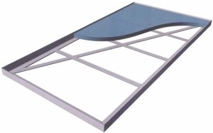
Hey Colton Modeller. This looks really great. Looks to be nice and rigid with that cross bracing. I can see various sizes here.
For those of us into "module" railroading, I assume it would be a piece of cake to fabricate some 2'x 4' or 2'x 6' module frames in aluminum? Because we travel with our modules from home to show or setup, we will need a system to fasten the legs to the frame. For wooden frames, we use a 5/16" threaded bolt drilled into the end of the wooden leg. The threaded bolt screws into a T-nut in the module frame. What kind of system would you have for the aluminum frame?
Are the pieces welded or riveted together? (I'm a neophyte with aluminum as I have only been using steel, so please excuse the basic question.) If riveted, how are they riveted? Would a "pop-riveter" do the job or is it more specialized? Could these be done up in kit-form which might reduce the cost?
Some questions that I'm interested in. The system looks good!
Bob M.
In addition to Bob's comments aout legs, modules need a way to be fastened together. With the wood frames, the "end plates" extend below the foam, allowing modules to be clamped or bolted together. Replacing the end angles with a "T" shaped piece could provide this capacity.
Andrew
Andrew
This is a totally modular system, so it's no problem to scale it from 2'x4' to 2'x6'. There are a lot of different ways to attach legs, but I think your method, railwaybob, would be applicable here as well - the T-nut would be replaced with a 6061-T6 (stronger alloy) nut welded to the inside flange over a clearance hole, and the foam notched so there was no interference.
I imagine it being welded for added rigidity, but there's no reason why the cross braces couldn't be a little longer & sit inside the angle bar so the whole thing could be rivitted - once the foam is glued in, it would likely be almost as rigid anyway.
I've gone through the numbers again, and we could do them welded for $85 each - it's cheaper for us to weld them than rivet, because there's less labor.
If you wanted a kit to assemble them youself, you might be better off just making them from scratch - you can buy the materials from a local metal dealer, or here http://www.onlinemetals.com/ and you can get a triple grind carbide tipped saw blade to quickly cut the material on a chopsaw.
As far as the mounting flanges go, aluminum T isn't as readily available as channel, so it's significantly more expensive - I would just cut a pair of 3" long pieces of the angle for each end, and weld or rivet them to the underside of the frame for a module-joining clamping surface. If you wanted to go all out, they could even have holes for bolts or registration pins to aid quick alignment.
Thanks, Colton; that's very much like what I had in mind. Delivered around $100, there's not much point in anything except welded construction, IMO. Welding aluminum is near impossible without the right equipment -- but with it, reliable and proven. That kind of construction should eliminate any question of warp or sag, no matter what's used for the top, so long as it's not soggy.
I don't suppose you're anywhere near the Bay Area? There are plenty of local shops with the capacity but it would be nice to deal with one in the hobby.
Ideal legs need some particular and somewhat conflicting characteristics. They should be very stable; they should be removable or foldable; they must be adjustable in height. I've spoken to module guys who have had considerable trouble with floor level in some exhibition halls; it would not be amiss to have adjustment over a very wide range.
One fellow sketched an idea for me of adjusters that didn't require bend and squat. The general idea was a long bolt off center from the leg itself, so that the top end could be turned with a socket wrench. I thought it a bit complex; also, that idea suffers from the difficulty that the leg now has an orientation. Murphy says that the adjuster will always be on the far side of the leg from you, except when it's in the way.
Others have had success with PVC pipe legs, although with centered, floor-level adjusters. Besides the bend and squat, I don't care for that design because the adjusters fit threads tapped into plastic endcaps on the pipes. I think, over that range of diameter, I don't like heavy loads on plastic threads.
My thought was to weld collars or couplers with internal threads to the module corners, perhaps a foot long. These would hold PVC legs with threaded ends. The entire leg can be twisted to make adjustments and one method serves for the entire range. A large nut or short coupler section on the threads is twisted up to the fixed coupler to lock the leg in place.
When the show's over, just unscrew the legs completely. During transport, the frame-mounted couplers act as stubby legs to keep the module off the ground.
My only concern with this approach is that there's no obvious way to add crossbracing between legs. Any sort of simple hole-and-bolt brace is in trouble as soon as the leg is given a slight turn.
I don't *think* PVC legs, even 4" dia., are going to be stable enough without any sort of crossbracing. Comments?
Official Free-mo Standard requires endplates 6" tall; for single main modules, 24" wide; for double mains, 26" wide. I'd thought a flat 1/4" plate be best welded to the end of each frame. This is not just about clamping area; the large mating surfaces force module-to-module alignment on two axes.
An issue is the relationship between endplates; it needs to be exact. Endplates need to be square and parallel to one another. I don't doubt that a good shop can handle this; they may want to perforate the endplate to get enough welding surface. What do you think, Colton?
Alignment pins are ideal but perhaps not always practical. Modules need to be located relative to one another to very close tolerances, so the bridge rails can be straight through the join and there is no kink at the rail joiners. The trouble is that modules may never see one another until the run session. If I were to drill alignment holes, I'd wait until track was in place, mate the modules by trial and error, *then* drill.
I suppose it could do no harm to specify alignment holes, so long as pins are removable. Modulers who follow the specs exactly will save setup time; those who don't, well, the pins come out and we fudge.