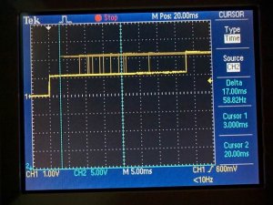
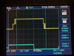
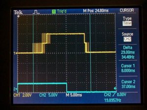
This next photo shows the time for a typical relay (Potter & Brumfield Tyco DPDT 12V coil, Digi Key part # PB384-ND) to react to a transistor switch, which simulates a microswitch that controls the coil current. Coil voltage was 12V as required by the relay design spec. The relay data sheet specifies under 10 msec for operation time, but this needs to be taken with a grain of salt as we shall see. The DigiKey catalog specs these times as 4.5 msec pull-in time (coil energized) and 1.5 msec release time (coil current interrupted).
Starting again on the left, the blue trace at the bottom of the screen shows the drive to the switching transistor, and thus the drive to the relay coil (the transistor propagation delay is negligible on this time scale). The yellow trace indicates the relay contact moving between it's two positions exactly the same way the turnout points operate in the previous post.
We can see that yes, it does take 4.5 msec for the relay moving contact to pull away from it's initial position when the coil is energized (each dot of the graticule dotted squares represents 1 msec) by the horizontal yellow line becoming vertical at 4.5 'dots' to the right of where the blue trace rises at the far left. This is the important parameter - how long it takes for the relay contact to get to it's open position. The brief horizontal portion of yellow is the time for the relay moving contact to travel between its two opposed end contacts, just like the turnout points between the stock rails. The completion of it's operation is shown when the yellow horizontal trace reaches it's upper level, the fuzziness on this vertical edge is the 'contact bounce' period when the vibrating contacts steady down from their sudden movement.
Already we can see that if we throw the turnout manually as fast as possible at 3 msec, the delay in relay response will give us a short circuit for a period lasting 1.5 msec. Not good. Best to keep that finger on the points a little slower.
One way to speed up the relay pull-in time is with a higher voltage to the coil, which could overheat it unless a shorter duration higher voltage pulse (from a capacitive discharge unit) is used for initial fast operation followed by a 'holding' voltage within the relay coil limit. The higher speed travel of the moving contact will result in more contact bounce, but we don't care about that.
The real trouble comes at the center to right side of the photo. The relay coil drive current is switched off at the center of the screen as shown by the blue trace dropping back down to 0 volts (the lower position). It takes a whopping 9.7 msec for the spring-loaded relay contact to open again as shown on the yellow trace returning to it's vertical center - but this is not the fault of the relay itself. I have placed a silicon diode (1N4002) across (in parallel with and in the direction such that the diode is reverse biased from the power supply) the relay coil which drastically slows it down from the specified 1.5 msec. This time duration is well within the faster manual operation times of the turnout and can result in much longer short circuit duration even at normal manual turnout operating speed, and the several amps of current flow from the resulting momentary short circuit (the turnout points complete their travel before the relay contact opens) can severely reduce the life of the relay contacts. This is worsened by the fact that a microswitch mechanical linkage will be adjusted to throw the microswitch when the turnout points are at their physical center of travel, not when they first break contact with the stock rails. The delay is caused by the coil discharge current (the magnetic field slowly collapsing) through the diode.
The diode protects the switching transistor, and should always be there even if a microswitch is used instead of a transistor to switch the relay coil. When the current to a relay coil (or any other electromagnet) is suddenly switched off, the suddenly collapsing magnetic field tries to keep the current flowing. Since there is an open circuit to contend with (if no diode is there to provide a discharge path for this current), the voltage spike that occurs from the coil can be several hundreds or even thousands of volts! This will instantly kill a transistor, and will cause terrible arcing at the microswitch contacts, reducing their life drastically. For proof of this effect, connect a 1.5 volt battery to a coil (relay, transformer winding, turnout motor) and hold the two bare wires in your hand when you disconnect the battery. OUCH!

Do NOT try this if you use a cardiovascular pacemaker, and use only ONE hand, not both so the voltage is not from arm to arm across your heart. Better yet, just take my word for it.
To return the relay release time to it's specified value, place a zener diode in series and back-to-back (banded end to banded end) with the regular diode across (parallel to) the relay coil. A zener diode works like a normal diode in one polarity, but when 'reverse-biased' against it's normal conduction direction will also switch on and conduct current once the applied voltage reaches the zener breakdown voltage. Zener diodes are available in many different voltage ratings, generally a 25-30 volt zener will fit within the typical 28 - 30 volts DC voltage rating of a microswitch. The coil-generated high voltage pulse will now be limited to the zener voltage, but the relay release time will be much faster, very close to it's specified time of 1.5 msec. Sorry, I don't have a photo of this yet.


