

Pantographs
- Thread starter Ray Marinaccio
- Start date
You are using an out of date browser. It may not display this or other websites correctly.
You should upgrade or use an alternative browser.
You should upgrade or use an alternative browser.
- Status
- Not open for further replies.
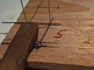
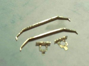
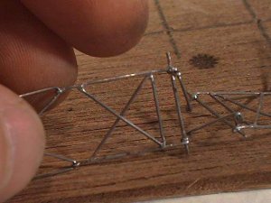
Fabricate the two equalizer arms from .020" wire as shown in the drawings.
To install them you must install the first one then turn the two assemblies 90 degrees as shown to get the other one to install.
Both arms must face the inside to give clearence for the locking tabs on the collector.
To install them you must install the first one then turn the two assemblies 90 degrees as shown to get the other one to install.
Both arms must face the inside to give clearence for the locking tabs on the collector.
Attachments
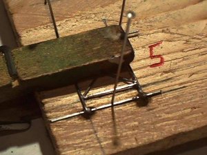
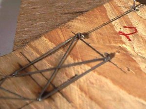
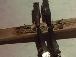
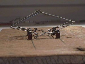
Install the mount brackets and temporarily mount the assembly to a peice of wood.
Trim the extra wire where the lower arm assemblies pivot.
The equalizer levers may need to be adjusted to make the ends of the lower arm assemblies lay on the wood block evenly.
At this point you will find out how accurate the mount brackets and lower arm assemblies are.
Trim the extra wire where the lower arm assemblies pivot.
The equalizer levers may need to be adjusted to make the ends of the lower arm assemblies lay on the wood block evenly.
At this point you will find out how accurate the mount brackets and lower arm assemblies are.
Attachments
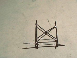
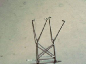
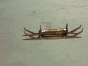
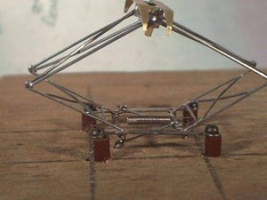
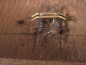
Install the collector.
You may need to file the ends that insert into the collector tube for it to opperate smoothly.
I had to do a little tweeking to get it straight.
Don't be afraid to twist it a bit, it may look fragile, but it's amazingly strong.
Adjust the locking tabs so they will latch onto the mount brackets.
In the photo I have one spring installed to show where they attach.
Attachments
This thread was moved to the Academy July 2005. Some posts were deleted to provide clarity and continuity the this important thread. It has been locked, so if you have any comments on this thread, please make them in the appropriate forum. Thanks.
- Status
- Not open for further replies.