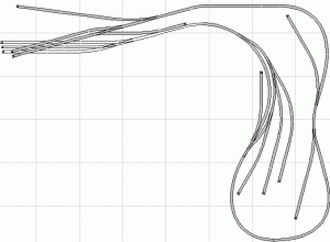
On drawing turnouts...

roryglasgow

Active Member
I've been experimenting with designing layouts with Paint Shop Pro--basically using the point-to-point line function to generate a vector object.

Those of you who use CAD programs... How do you draw your turnouts? Do you just estimate it, or do you have a system or some kind of template?

Thanks!

-Rory
 
CAD & turnouts, etc

I use VersaCAD, a professional-level CAD system that --- although it's been off the market for 10 years --- is still superior to AutoCAD.

As in most higher-end CAD programs, you can create symbol libraries in VersaCAD. I have a library containing pre-drawn symbols for the various size turnouts (normal and "Y") and also for curves with easements, tunnel portals, etc. This really saves a whole lot of time, and guarantees accuracy.

I'm not familiar with your CAD system, but if it is sophisticated enough to allow you to create and use symbols, it would be worth your time to teach yourself how to do it. With VersaCAD, all you need do is draw the thing once, save it alone as a drawing, and then add it to a symbol library. But that was one of the beauties of VersaCAD, that most other systems don't offer.

Bill
 

roryglasgow

Active Member
Thanks for the info, Bill. That answers my question. I'm not actually using a CAD program. Paint Shop Pro is a drawing program. But one of the features it has is that lines and shapes can be drawn as vector objects, which means that they can be curved and shaped into whatever you desire. I was experimenting with drawing lines to represent track when I realized that I didn't have an accurate means of representing turnouts!

I'll do some more brainstorming to see what I can come up with, but I think that at best I can only roughly sketch a track plan with this software...

-Rory
 
Ah, yes. I do know that Paint Shop isn't CAD. I got my mind stuck on CAD. I've never used paint programs, so really don't know, but I wonder if you could create a fairly close image of a turnout symbol as a drawing, and import it, and rotate it to fit wherever you want it in a track drawing.....

In my experience the place where people most often go wrong in designing track plans is not getting the turnout angles right, and not allowing enough space for the points, frogs, etc, before introducing curves, or other features. I've even seen this in published track plans, where one might dare to think the originator should have known better.

Another thing that bugs me on many track plans published in MRR and RMC, is they frequently show track center lines way too close to the table edge. I use a minimum of 3 inches there (in HO) and really prefer 4.

Bill
 

billk

Active Member
Bill (S) - How did you create your turnout library? Did you take measurements from actual model turnouts? Thanks, Bill (K)
 
Rory,
In the past I tried using Autosketch (a chopped down version of Autocad). In using a CAD package it is very easy to get lost with all the constuction lines you would have to create to get things right.

Pains shop pro is much the same as using a pencil and paper but has the advantage of adding some colour to your drawing.

I've found that Atlas's RTS 5.0 (free download) is probably the best tool for getting a layout down onto paper. Once you have the layout drawn you can use PSP's "Photo" function to grab the layout area of the screen. Then you can add whatever you want using PSP.

Although RTS has fixed radii etc, when it comes to actually building the layout one usually finds we go our own way regardless of the original plan. (Does this make sense? :) )

Errol
 
To Bill (K)....
I used the NMRA turnout drawings and guidelines as a general reference, and for the frog angle just used the "rule" that a #4 turnout diverges 1 inch in 4, a #6, 1 inch in 6, etc. But I plan to hand lay the turnouts on my next layout. (I'm in a fairly long period "between" layouts just now.) If I was planning to use purchased turnouts, I'd buy a sample of each and take my measurements directly off them. Somehow each manufacturer seems to get different angles from "1 in 6"!
I've seen advice to people who hand lay turnouts to just "build them to fit," but unless you are fitting them to standards, you're liable to wind up with #3's which I doubt would work very well unless you're modeling trolleys.

To Kettlestack....
I've never used any of the AutoCAD products for track layout, but having used A'CAD and A'CAD Light for general drafting, I cannot imagine what you mean by construction lines. A really good CAD program (I'd rate A'CAD as a fair CAD program) is really the ONLY way to effectively create a dimensionally accurate "engineering" drawing, other than drawing it by hand. The rub is that good CAD is expensive, as is a good plotter that can output the drawings on large size paper (24x36 or larger). And beyond that, they can take a whole lot of time and commitment to learn to use. I'm fortunate in that as a design engineer (now retired) I learned to use them and aquired the equipment professionally.
I downloaded the Atlas software out of curiosity, and gave it a try. But it is so limited and so limiting in what it does (at least compared to professional CAD) that I gave up on it. The price is right of course, but I suspect it would take as long to learn as real CAD, so my suggestion is to find someone with AutoCAD (or if you're REALLY lucky, VersaCAD) and "borrow" it, if you really want CAD.
Or, if the time to learn CAD is impractical, the model railroader could buy a drawing board, T square, and some triangles, and teach him/herself to draw. More years ago than I like to remember --- before I had any design or engineering training --- I did just that, and even wound up designing a fire station for a city in Oregon that WAS built, and IS in use today. (Ah, the recklessness of youth. Now I shudder to think of all I DID NOT know then!)

Bill Stone
 

roryglasgow

Active Member
Errol,

I use Atlas RTS, too, but like Bill (S) said, have found it limiting. I was mainly looking for a better way to lay flex track on a design. I did try using images of turnouts from an RTS drawing to create scale drawings of turnouts in PSP. That can get a little tedious, though!

Well, it was just an experiment. I like RTS, though, because I can quickly sketch something out. To me, it's the easiest of the layout programs available. Attached is a layout I put together based on the Mount Galena Mines Railroad from Small, Smart & Practical Track Plans. This version is in N scale, but it occupies about the same amount of space. I was able to put this together (including inclines) in about 20 to 30 minutes...while talking to my wife! :)

And yeah, the ability to print at 1:1 scale is really handy! Before I started my layout, I printed the whole thing in 1:1, cut out the track, and taped it to the top of the table to better understand where everything was going to go. It was pretty close to the real thing!

-Rory
 

Attachments

  • mount galena mines railroad in n.gif
    mount galena mines railroad in n.gif
    11.8 KB · Views: 131
Rory,
That's a good drawing. Trying to get precision into a drawing for track is, to me, pointless. Such a drawing as yours is sufficient to let you know "it will work". (Chuckling again here) "Close enough is good enough" :)
Not sure that track plan can rightly be called "Small" though.
Is it the basis of your next major project?

Errol
 

roryglasgow

Active Member
The original is in HO-scale and is 8' x 10'. My version doesn't reduce it directly. Instead, I tried to fit the N-scale track into about the same space. It could probably be done in about 4' x 5', or maybe just a little bit larger.

I'm giving this design (or something along those lines) some consideration. Like I said in another post, this one has actually gotten me to thinking about going to HO-scale--mainly for the greater availability of steam locomotives and old-time structure kits.

But now I'm tinkering with the idea of building my own shell for an N-scale Shay, maybe based on the Greenmax mechanism (or preferrably something better) that Small Scale Logistics uses for their kit. The SSL kit looks pretty rough to me, and for the price they sell if for, I wonder if I can do a little better...

Just a few ideas for future projects!

-Rory
 
I have found graph paper to be an excellent tool for initial layout design. It is available in 12 squares per inch and one square per inch and everything in between. Using several sizes allows you to see the overall and details. (overall on 12/1 grid, detail on 6/1 grid)

I drew my table layout on graph paper and used the grid as a guide for turnouts, straights, elevation changes and curve radii. When I transfered it to 1:1 the greatest deviation I had was 1/4".

There is no substitute for pencil and paper.
 

roryglasgow

Active Member
Yeah, Yakko, but I'm a Computer Geek. Plus a sheet of paper can't play MP3s and receive e-mail. There may be "no substitute for pencil and paper," but computers are lot more cool. :)

-Rory
 
I have to admit, it is difficult to play an MP3 on a piece of paper but I have a great turntable and a killer power amp. I hate the sound from those dinky pc speakers. Besides, I can't find any Bix Biederbeck cds anywhere! and NIN just doesn't feel right unless my ears are bleeding!

The only things I use my computer for are this board, e-bay and downloading porn.;)
 
Bill (Stone),

I can't imagine how I missed reading your post just prior to Rory's drawing ... (must be an age thing :) ). I agree with you on just about every count. I had the opportunity to get Autocad for use at work but declined it because of the extensive learning process.

Autosketch enabled me to re-layout the whole of the factory I worked in over a period of 13 years as I had transferred to site maintenance dept.

When one uses flexi track one needs construction lines to draw turnouts at a tangent to the ends of the flexi track etc. Anyway, I just don't use it for anything except designing buildings for my layout.

Errol
 
S

siddisoza

Thats hard to do because the diverging track in a turnout aint a smooth curve. Even the Peco turnuots which are being discussed in another thread honestly have a short straight section where both routes converge, though after that the diverging route is a constant raduis.
 

Bill Nelson

Well-Known Member
Paper and pencil

I am a paper pencil and pen guy also. I start with a very detailed drawing of the room I', working with on graph paper. I put a lot of work into that, and when it is right I make lots of copies of it, same the original and draw only on the copies.


I usually start with planning the aisles, and go from there to the tracks. I work with a compass and straight edge to get the track center line, and then overlay that with a carpenter's pencil trimmed to make a line as fat as the track will be. I have little scale drewings of standard car and locomotive sizes to help keep me honest, and some gauges that show minimum track clearances to help keep me honest. If I have one section of a layout that I am satisfied with, I draw it very carefully in ink on index card stock, that way I can set it down on a blank room plan copy, and try fitting other elements to that section without having to draw that one section over and over again.


This way several competing plans can be developed and viewed side by side. In making the curves I mark the center point of the compass with a little cross and indicate the radius, and this make it easy to transfer the plan to plywood to cut the sub roadbed. I hand lay my switches, so it is very important to leave enough room. On a small portable switching layout, I once had a #2 1/2 Y stub switch. I could get a small Consolidation through it, but it was pretty harry. I want #6 switches If my equipment or trains are anything but tiny.


Bill Nelson
 
Top