Fixed.
I made a temporary re-connection of the red wire but didn't get any response from the decoder / lighting. I cut the old decoder out and temporarily wired in a fresh decoder and found, to my relief, that the lighting circuit / lights were working.
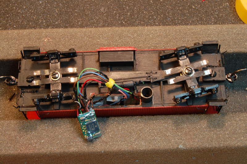
Out of curiosity, I tested the old decoder by itself and found that it also worked. I'm not sure why it didn't work with the temporary connection. Through this process, I soldered extensions onto red and black power leads and the blue, green and purple function wires to make the testing easier. My guess is that during this process, I cut out an unseen non-continuous wire.
This photo is after all is put back together (and working) with the original decoder prior to stuffing everything back in. Note the condition of the black insulation!
After one more test to make sure reinserting the decoder and wiring didn't cause any problems, I resealed the bottom:
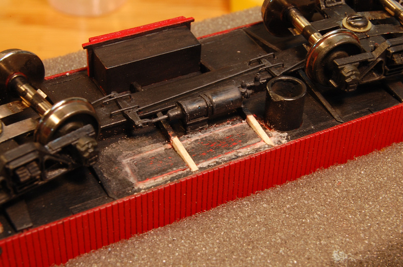
and got started on the last detail - sheathing bolts in the cupola area. The bolts were from the Details Associates #550 caboose kit. Because I didn't trust eyeballing the locations - and the fact that I now have two more caboose models waiting in the wings, I made a drill template for the bolt locations from an index card:
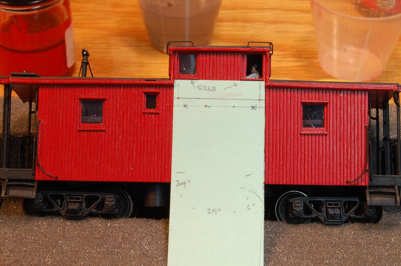
The locations were determined from photos - I measured the wheel diameter in the photo with dial calipers, then divided that by 33 (the real-live wheel diameter, in inches)to get a conversion factor. Then I was able to locate the bolts relative to the window sills by dividing a photo measurement by the conversion factor. THEN I eyeballed it to make sure it looked right prior to actually drilling.
I may put one more photo in with the lights on, but this more or less wraps up this construction thread. One benefit to this thread will be for me - I can use it as a guide to remind me what to / not to do with the two additional models!
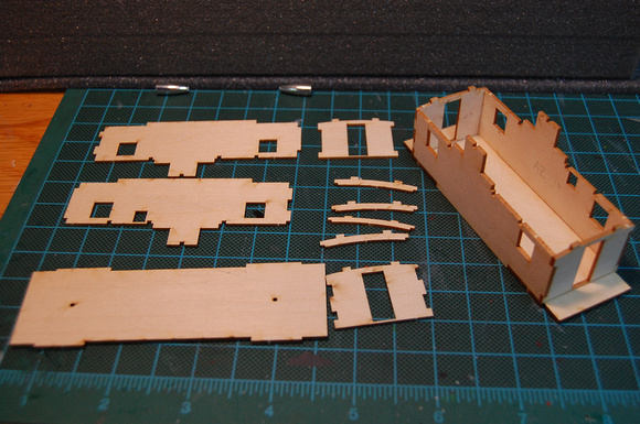
Overall, I'm very pleased with this kit - it was much easier to assemble that a box of sticks, but was a better solution than RTR (which doesn't exist!). This is my first laser cut kit of any kind and I was pleased with the accuracy of the cuts and the peel and stick parts worked very well - I was suspicious of this feature. Instructions were very good.
The downside, in my mind, is the lack of included detail that was recommended by AMB, but not included (detail kit, trucks, couplers, etc.).
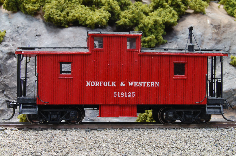
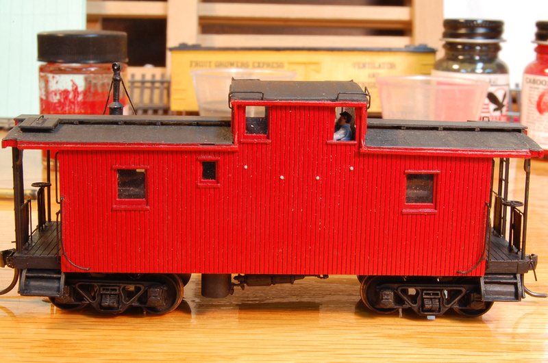
So, the last photo of this thread is the current state of the cab - compete less lettering. Once that's complete, I'll put another entry into the Fluesheet's Builder's Photos thread
Matt
<edit - Removed one dead link due to removal of the photo from the source gallery>
I completed some exploratory surgery this evening and found that the red pick up wire had sacrificed itself to the short gods. Who knows, the decoder may be OK. The worst case will be if wiring somewhere upstream of this has been damaged. I'll have to resign myself to no lights if that's the case.:cry:
I made a temporary re-connection of the red wire but didn't get any response from the decoder / lighting. I cut the old decoder out and temporarily wired in a fresh decoder and found, to my relief, that the lighting circuit / lights were working.
Out of curiosity, I tested the old decoder by itself and found that it also worked. I'm not sure why it didn't work with the temporary connection. Through this process, I soldered extensions onto red and black power leads and the blue, green and purple function wires to make the testing easier. My guess is that during this process, I cut out an unseen non-continuous wire.
This photo is after all is put back together (and working) with the original decoder prior to stuffing everything back in. Note the condition of the black insulation!
After one more test to make sure reinserting the decoder and wiring didn't cause any problems, I resealed the bottom:
and got started on the last detail - sheathing bolts in the cupola area. The bolts were from the Details Associates #550 caboose kit. Because I didn't trust eyeballing the locations - and the fact that I now have two more caboose models waiting in the wings, I made a drill template for the bolt locations from an index card:
The locations were determined from photos - I measured the wheel diameter in the photo with dial calipers, then divided that by 33 (the real-live wheel diameter, in inches)to get a conversion factor. Then I was able to locate the bolts relative to the window sills by dividing a photo measurement by the conversion factor. THEN I eyeballed it to make sure it looked right prior to actually drilling.
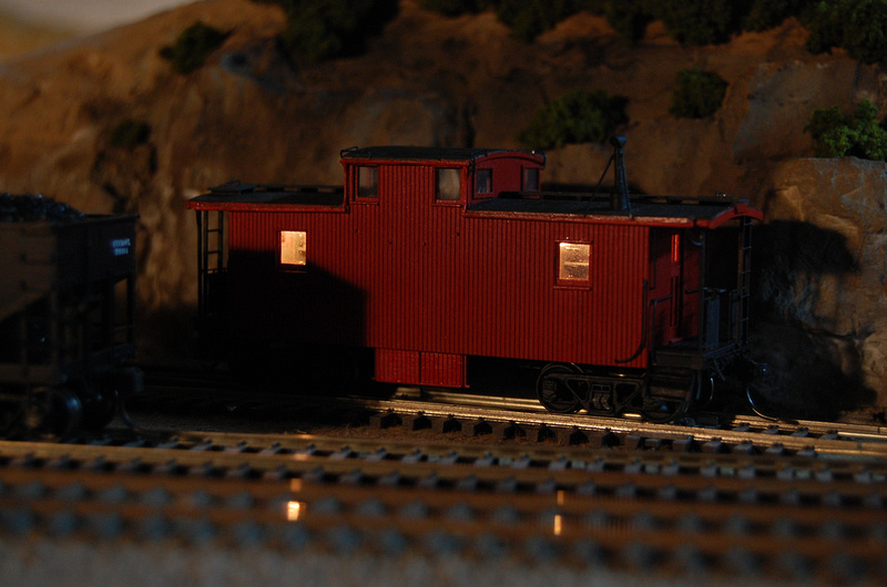
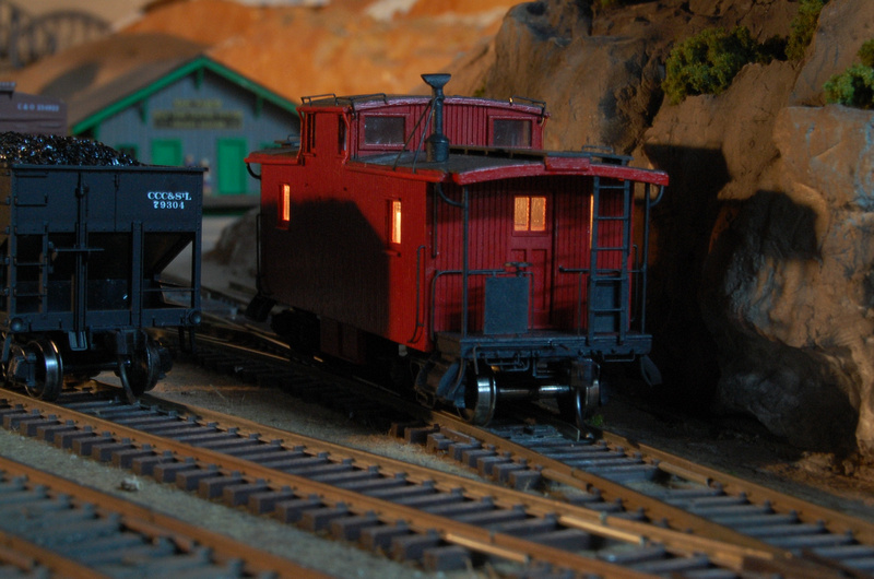
I may put one more photo in with the lights on, but this more or less wraps up this construction thread. One benefit to this thread will be for me - I can use it as a guide to remind me what to / not to do with the two additional models!
Overall, I'm very pleased with this kit - it was much easier to assemble that a box of sticks, but was a better solution than RTR (which doesn't exist!). This is my first laser cut kit of any kind and I was pleased with the accuracy of the cuts and the peel and stick parts worked very well - I was suspicious of this feature. Instructions were very good.
The downside, in my mind, is the lack of included detail that was recommended by AMB, but not included (detail kit, trucks, couplers, etc.).
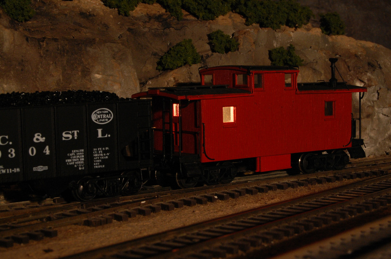
So, the last photo of this thread is the current state of the cab - compete less lettering. Once that's complete, I'll put another entry into the Fluesheet's Builder's Photos thread
Matt
<edit - Removed one dead link due to removal of the photo from the source gallery>

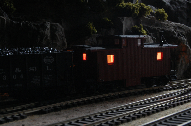
 Since this particular decoder has four outputs, you could also go so far as to add marker lights on one end or the other and control them independently; either by manually turning one end on and the other off, or setting the functions to be directional. In the latter's case, you would have to "reverse" the caboose via the throttle - identical to directional lighting on a locomotive. I, however, wasn't willing to go there - and in any case, am not sure if the pieces parts are even available.