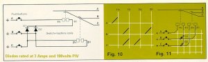
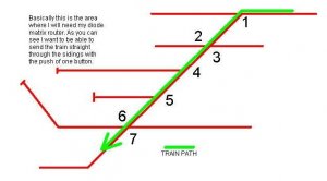
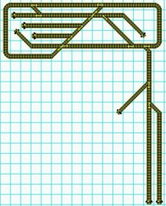
Errol (and Bob) I took a look at the required matrix last night and designed one that has 9 routes. I made some assumptions regarding track usage, primarily that the track to the right of the ladder and just below the main would be used as a switch lead. Bob has told me offlist that what appear to be doubleslips are in fact two regular turnouts. I guessed at their arraingement and will mail to Bob today. Based on my assumptions, traveling right to left on the main there will be three options, stay on the main, take thru siding (track 1 on my diagram, Bob) or travel down ladder to what seems to be a reverse loop track. I have not provided for trains off the main to travel down what appear to be stub ended sidings. These are routed from the switch lead instead. The routings I created require 27 diodes. Errol is right about switches welding themselves together when breaking the contact, and there are seven coils to throw for one route, the one Bob was asking for in the first place. I do not use switches, I use stud and probe, as Shamus does. Again, I leave cap discharge to others, they've been used for decades by multitudes so who am I to argue? I get by without one but I have a heavy duty power supply. Pushbutton switches probably wouldn't survive on my railroad. I tried a Rix pushbutton once, it lasted one throw!
Bob, the drawing I send you shows the diodes coming off the coil contacts. Since there are so many, it may be easier to mount them on perf board and solder leads to them at your workbench rather than soldering them under the layout. As long as the connections remain the same it won't matter which way you go. For instance, coil D on the drawing has 5 diodes, they could be side by side on perf board, tied together on one end and run to the coil, with 5 leads on the other end going to the studs/switches for the appropriate routes.
Gary