How to use a VOM on your layout

Status
Not open for further replies.

ezdays

Out AZ way
Jim Currie suggested that I do a tutorial on the use of a VOM. His thinking is that every modeler needs this tool, and should know how to use it. A VOM is indispensable for use during wiring and troubleshooting layouts and accessories. This meter is an electrical device used to measure Volts and Ohms, thus the name, volt-ohm meter (VOM). Most meters now measure amps, continuity and some even measure capacitors and test transistors. There are two types of these meters, one is analog where the value of what you’re measuring is shown by the position of a needle on a dial face, and the other has a digital readout. Finding an analog meter is difficult nowadays, so we’ll talk about the digital type.

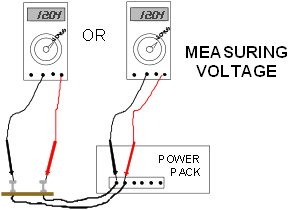
Let’s spend a little time discussing what is it that we’re actually measuring. Volts are the amount of electrical potential between two points, kind of like the amount of water behind a dam, the higher the water, the more potential there is. There is AC (alternating current) volts and DC (direct current) volts. AC is what you get out of the wall socket in your house and is normally created by a generator. Current flows back and forth 50 or 60 times a second. DC volts are what you get out of a battery or a power pack that has change AC into DC. Current flows only in one direction in this case. There is another tutorial on power packs here might want to read.

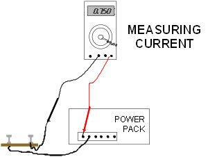
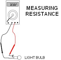
Voltage by itself can do nothing. You can frequently measure voltage between yourself and a water pipe, but it is normally harmless. Notice I said “normally”. If you measure a few volts between you and the pipe, that’s what’s know as “AC pick-up”, if you measure a lot higher, say 110, don’t touch the pipe, that’s not a good thing. What is required is current, measured in amps, to get any work done. Think of this as the water pressure that flows through the pipes leaving the dam. Resistance, measured in ohms, is the ability to oppose the forces of electrical current. This would be the same as when the water pressure hits a restriction or narrowing in a pipe, lowering the water pressure. Or in our case, lowering the amount of current that flows. There is a relationship between these and can be expressed in a formula know as ohms law:

Voltage equals Current times Resistance, or, E = I x R.

If you know any two values, you can calculate the other one using this basic electrical formula. “E” is used to denote voltage and stands for “Electromotive force”.

Power is the Voltage multiplied by the Current, or P = E x I, and cannot be measured using a VOM.

There's a thread with a link on Ohms law that is worth looking through as well.

A basic meter looks like these:

MetersR.jpg


You can purchase an inexpensive meter for under $10US, and up to a couple of hundred dollars for a very sophisticated instrument. The one on the left I paid about $3 for on sale at Harbor Freight, the other two were about $40-50 purchased at an electronic supply house. There is no need to spend more than that. All meters are set up about the same. There’s an on/off switch somewhere, holes at the bottom for probes, a digital readout and a large switch used to set the meter to select what you are measuring. Make sure the meter is set for the measurement you’re about to take and at least the highest value you expect to see. Remember, the numbers on the meter selection switch represents the highest value that can be read in that switch position. Also, make sure the two probes are in the correct holes for what it is you are measuring. You can damage the meter if you have it set for 20 mA and you are measuring 2 amps or if you’re measuring voltage and the meter is set to measure resistance. Each meter is different in some respect. The meter on the right is self-seeking in that you can just set it for what it is you’re measuring and it will seek the proper scale for the value. To me these types of meters are confusing. The smaller meter does not measure AC current and has limited range positions.
 

ezdays

Out AZ way
Measuring Volts:

When wiring up anything, it’s the wires that bring the voltage to wherever it’s needed. In our case, the wires go from the power pack to the rails (maybe through a control or switch panel), then to the loco’s motor. If you don’t have voltage, you don’t have anything. When testing, I always start at the farthest point. If I don’t have voltage there then I check the power pack. If I have voltage at the source, then I can work back in either direction to locate the point where I have voltage on one side, but not the other. In the case of rail wiring, it’s necessary to move both probes as you go since there is no common connection (or grounds) in DC rail systems. When measuring DC voltage, there is polarity, the red probe goes to plus, the black to minus. If they are reversed, the meter will read a minus (-) in front of the value. Remember, if you don’t have a load, you will read the same voltage all along the line, that can change when you add a loco or a light somewhere.
 

Attachments

  • Volts.jpg
    Volts.jpg
    24.5 KB · Views: 732

ezdays

Out AZ way
Measuring Current:

There is no current on an open circuit. Once you add a load, or some resistance in the circuit, you will generate current. The lower in resistance the load is, the higher the current. The higher the voltage, the higher the current will be for the same load. That’s why when you increase the voltage from the power pack; the current increases and the train will run faster. Current is always measured in series with the load, that is, you must connect the meter in line with one of the power wires. Remove one wire from the power pack; connect one probe to the power pack, the other to the wire you just disconnected. Set the meter to the highest current setting. On some meters that will require moving the positive probe to a different probe hole. There may be a fuse in the lower settings while a setting of 10A or more usually aren’t fused.
If for instance you want to find out how much current your new loco draws at slow speed, adjust the power pack to the setting you want and put the loco on the track. Turn on the power pack and read the meter, if it’s too small a number, you may have to lower the meter setting. If the meter value keeps changing as the loco goes from one section of track to another, that’s a good indication that you have some rewiring to do. It could mean that a rail joiner is not making good electrical connection or that you need to add a new voltage drop to the rail section that is affected. Undersized wire will cause these problems as well. As you increase the speed setting on your power pack, the current will increase as well. If you have a lamp connected to your power pack, as you increase the voltage, or speed setting, the lamp will get brighter and the current will increase. The total current at the power pack is equal to the sum of all the currents required by all the loads you have. Let’s say you have two locos and at the 50% speed setting, they each draw .250 amps, and you add four lights, each drawing 50 mA, or .05 amps. Your total current draw will be 700 mA or .7 amps. You have to check the label on the power pack to see what the maximum output is. Some are rated in amps, others in watts, or power. If you exceed the rating, one of two things will happen. The unit will shut down until the load is removed and or the power pack it reset, or on some cheaper units, the voltage will drop to compensated for the increased current and it will heat up. Some have thermal overload protection, but the ones that don’t can be damaged this way, so whatever you power pack is like, it’s best to know how much current it can safely deliver and how much your equipment is loading it.
 

Attachments

  • Current.jpg
    Current.jpg
    19.4 KB · Views: 730

ezdays

Out AZ way
Measuring continuity:

Frequently, when troubleshooting wiring, it is easier to use the resistance setting on the meter to test continuity or a short. One word of caution, do not measure anything on the ohms scales with power on. It is best to just disconnect the wiring to the power pack. Many meters have a continuity setting that is denoted by a musical note next to the switch position. With the meter set for that, the meter will buzz whenever the two probes are touched together. If your meter doesn’t have that, then use the lowest setting for ohms. A short will then show as “0” and an open circuit as a “1” on the left.

To test for a short between the rails, connect one probe to one rail and the other probe to the other rail. If the power pack is disconnected, you should see an open circuit. Note that if you have some lamps in the circuit or have the power pack still connected, you will see some resistance, but you shouldn’t see a short circuit.
To test for an open circuit to your rails, connect one probe to the end of the wire that went to the power pack, and touch the other probe to the closest rail where the other end of the wire is connected. You should see a short. Run the probe down the rail and you should see a short all along the rail. If at any point the meter shows an open or high resistance, you have located a problem area. If you have a switch or control panel in the circuit, you’ll have to be sure the switches are in the right position. You should repeat the process with the other wire and rail.
 

Attachments

  • Continuity.jpg
    Continuity.jpg
    20 KB · Views: 728

ezdays

Out AZ way
Measuring resistance:

Everything that uses electricity has resistance. For the most part, you shouldn’t care. If you know the voltage and current ratings of things, you can calculate the resistance. On the other hand, if you know the resistance and the voltage, you can calculate the current. If for instance you have a 5 volt lamp that you want to use in a 12 volt circuit, you need to know either it’s current rating or it’s resistance so you can put a voltage-dropping (or current-limiting) resistor is series with it so as not to damage the lamp. Set the meter to one of the ohms scales, in this case a lower one. Touch each probe to one of the lamp contacts or wires and read the meter. Let’s say it reads 50 ohms. Using the formula above, you can calculate that it takes .100 amps, or 100mA to light. You’ve got to use a series resistor with a value that will drop 7 volts across the resistor and the remaining 5 volts across the lamp. Using that same formula, you can determine that you need a 70-ohm resistor, or a standard 75-ohm resistor. In this case, a one-watt resistor would be necessary. You can use the resistance scales to check continuity as described above. This is a good way to do it since it can show when you have a connection, but a poor or high-resistance one. If you’re checking continuity on your rails and you’re getting 0, or a short, then your OK, if you see a higher number like 100 or 1000 ohms, you can have either a poor solder joint, a corroded rail joiner or even a dirty track.
 

Attachments

  • Resistance.jpg
    Resistance.jpg
    15.2 KB · Views: 772

ezdays

Out AZ way
I hope this helps those of you that are reluctant to use a meter to set up and troubleshoot your electrical wiring. It isn't difficult and can save you hours trying to locate a problem with you wiring. Be aware that VOM's can be used to troubleshoot most any electrical problem not only on your layout, but at home, on your vehicle or a simple electrical appliance. Remember though, electricity can be danerous, so when working with higher voltages such has house wiring or appliances, use caution and extreme care. If you aren't sure about what you're doing, then don't do it, it's that simple and that necessary.

If anyone has anything they'd like to add, or see something that isn't clear or needs changing, please let me know.

Thanks,
 

jim currie

Active Member
:) nicely don Don. I might add that for my layout use i prefer a analog meter but as you say there getting hard to find I have had the triplet i use on RR for over 30 years :)
 

ezdays

Out AZ way
jim currie said:
:) nicely don Don. I might add that for my layout use i prefer a analog meter but as you say there getting hard to find I have had the triplet i use on RR for over 30 years :)
Yeah, I've got a Simpson 260, that used to be the industry standard that I used for years. I bought it 1970 and it was old then. :rolleyes: I don't use it, I keep it as a momento of years gone by...:wave: :wave:
 

caellis

New Member
Don, nice job.
As a side note I find almost any DIGITAL VOM will also correctly read DCC. I have expensive digital meters and a cheapo like the one you show also from Harbor Freight.
The cheapo works pretty good on DCC but of course is not quite as accurate.

Anyone using DCC should own a digital meter.
 

ezdays

Out AZ way
caellis said:
Don, nice job.
As a side note I find almost any DIGITAL VOM will also correctly read DCC. I have expensive digital meters and a cheapo like the one you show also from Harbor Freight.
The cheapo works pretty good on DCC but of course is not quite as accurate.

Anyone using DCC should own a digital meter.
Accuracy is not that important in most cases. a couple of percent is close enough for RR work, and for house and vehicle work as well. They're claiming that little meter is 1.2% on volts and amps, around 1% on ohms.

I bought four of them when they were on sale for under $3. Someday My plans were to incorporate them into a dual cab control panel so I can permanently monitor volts and amps. The longer I put that off, the less likely it's going to happen.:rolleyes: :rolleyes:
 

jim currie

Active Member
Don got one of the boat anchor Simpson's about the size of a small suitcase:) i like the triplet because its smaller than a pack of smokes and is tough.
 

ezdays

Out AZ way
jim currie said:
Don got one of the boat anchor Simpson's about the size of a small suitcase:) i like the triplet because its smaller than a pack of smokes and is tough.
Jim,

I also had a Textronix 535 oscillosope, so let's not hear about a Simpson 260 being a boat anchorsign1 sign1

I finally got tired of lugging it around and when we moved seven years ago, I couldn't sell it I couldn't give it away so me an four other guys we able to lift it up and throw it in the dumpster.:D :D
 

caellis

New Member
ezdays said:
Accuracy is not that important in most cases. a couple of percent is close enough for RR work, and for house and vehicle work as well. They're claiming that little meter is 1.2% on volts and amps, around 1% on ohms.

I bought four of them when they were on sale for under $3. Someday My plans were to incorporate them into a dual cab control panel so I can permanently monitor volts and amps. The longer I put that off, the less likely it's going to happen.:rolleyes: :rolleyes:

I realize the accuracy of the cheapo digital meter is more than adequate for our purpose in MRR. I guess I am embarrassed that this so called cheapo meter is nearly as accurate as my meter that cost about 50 times as much as little as 5 years ago!

I have wired one of these meter into each of my 4 power districts (similar to DC blocks). I powered them with a 9vdc wall wart. This lets me see any voltage fluctuations between the districts. Kinda over kill but I like meters and buttons!
 

hooknlad

Member
Kudos to Don !!!

Don -great post !! I don't think Mr "Simpson" could've done it any better with an explanation - Bravo !!!!

Just one lil interjection - When using a VOM to test any High Voltage , 50 volts or better, It is a wise safe practice to always test your VOM on a "known" live circuit , Then test what you are looking for the voltage of, then go back to test the "known" live circuit . Many people take for granted that the VOM is 100% reliable. I make it a practice to do this test, each and every time I use my VOM. Even if I goto lunch and had used the VOM just 30 minutes earlier, I re-test my VOM - Things could change in that short time. Batteries die, etc... In my line of work, My co-workers and I rely on knowing if the circuit is either definitely ON or Off. " I dunno's " just don't cut it when lives are on the line.

One other thing - No matter what you are testing, if your VOM is not self adjusting, always set your VOM to the highest setting, then gradually set the range lower, this will keep your VOM on its toes and prevent its premature demise.

Keep Up the great Lessons !!!!!
 

ezdays

Out AZ way
Good point Michael, it is always best to be safe. Meters are for the most part reliable and you can tell when one is not working. Not so for people. :rolleyes: How many times have you had someone "borrow" your meter when you were away and not tell you, and then return it on different settings? Not cool. :curse:

One thing I always have done, especially when dealing with higher voltages is to disable the source and put tape over it with a note "do not turn on circuit"... Secondly, I always treat a circuit as being live until I'm positively sure that I know it isn't.

As I said in my tutorial, I hate self-adjusting meters. When you're working with a normal meter, you know what scale you're on. With a self-adjusting meter, it changes ranges by itself and you have to keep track of the decimal point. I looked at one of those meters and saw 100 volts on it and jumped, until I realized it had scaled down and I was reading 1.00 millivolts, or just noise.wall1
 

jim currie

Active Member
Don i have to agree whole heartly with you and Micheal having worker live circuits up to 12.5kv safety is a issue that should be addressed first time every time, as you said treat every circuit as live till you know better 110 might not kill you but it can ruin your day:)
 

kf4jqd

Active Member
That was a good post. I agree, if you use electricy as part of your hobby. You need to know how to use one. I have both analogy and digital. They both have their advantages and disadvantages to each other. Here's another test equipment you might concider, a logic probe. This would be very useful when you are working with DCC.

Andy
 

kf4jqd

Active Member
It's not the voltage that kills you. It's the currant (amps) that will! :( I have worked on a vaccum tube ham radio ampifier. I forgot to discharge the high voltage circuit. Laid a steal screw driver on the hot side and to ground. 75,000 volts ran through me. Shot across the room! Thank God the amps was very low, under 1/4 amp. I wouldn't be here today if it was any higher! Model railroaders don't deal with this high voltage on a regular basis. If you feel uncomfortable about high voltage (above 30vdc), you may want to contact someone who is.

Be safe,
Andy
 
Status
Not open for further replies.
Top