

I am to the point of building bridge supports to hold up yhr point of intersection of a ME bridge and a Atlas bridge. Here is a quilc Idea of one I did using paint. I am thinking of putting one flat piece (of styrene) holding up the Atlas (on the left) and another holding up the ME, and then guing them together. There would be legs of some sort holding up the whole thing. In the drawing the bridges are the two red blocks sepperated by a black line, and the leg setup is grey and individual pieces are outlined in black. How does it look? Any suggestions? Please comment I have never done this before and I want to make sure It will hold up my trains.
How to build bridge supports
- Thread starter Kevinkrey
- Start date
You are using an out of date browser. It may not display this or other websites correctly.
You should upgrade or use an alternative browser.
You should upgrade or use an alternative browser.
Kevin, if you change the format of your image to a jpg, it'll be easier to view.
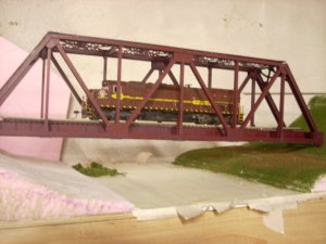
Here are a couple of photos showing methods of joining bridges from different manufacturers.
The first is an M.E. tall viaduct with an Atlas deck truss spliced in. The short M.E. girder atop the tower sits on the I-beam that comes with the bridge kit - that brings that girder up to the same height as the one closest to the viewer. At the far end of the tower-top girder, there's another smaller I-beam sitting atop the larger one - this supports one end of the Atlas truss bridge.

On this bridge, the same types of bridge spans are used, but they're sitting atop concrete piers. I used Evergreen styrene H-columns, I-beams and angle to make the supports shown, and, as you can see, the Atlas span is again resting atop an I-beam sitting on the support structure. The various shapes are held together with splice plates made from sheet styrene.

These bridges have easily supported trains of more than 6 lbs., and I wouldn't hesitate to put even more weight on them.
Wayne
Here are a couple of photos showing methods of joining bridges from different manufacturers.
The first is an M.E. tall viaduct with an Atlas deck truss spliced in. The short M.E. girder atop the tower sits on the I-beam that comes with the bridge kit - that brings that girder up to the same height as the one closest to the viewer. At the far end of the tower-top girder, there's another smaller I-beam sitting atop the larger one - this supports one end of the Atlas truss bridge.
On this bridge, the same types of bridge spans are used, but they're sitting atop concrete piers. I used Evergreen styrene H-columns, I-beams and angle to make the supports shown, and, as you can see, the Atlas span is again resting atop an I-beam sitting on the support structure. The various shapes are held together with splice plates made from sheet styrene.
These bridges have easily supported trains of more than 6 lbs., and I wouldn't hesitate to put even more weight on them.
Wayne
Thanks, I think I will pull out some paper and draw up some plans for supports using styrene shapes, I assume you glue the bridges to the supports right? And how did you attach track to your ME bridges, it says to use CA, what exactly is it, I use solvent or plastic cement on all my models?
That's correct: all of the bridges in the structure are cemented to one another and to the support towers, and can be lifted out as complete units. I use lacquer thinner to cement styrene to styrene, and it works as well as commercially available styrene cement, but is considerably cheaper. To cement Micro Engineering bridge track to styrene bridges, you'll need to use either ca (Krazy Glue or a similar hobby product) or contact cement, as the M.E. ties are not styrene plastic.
Wayne
Wayne
I second the use of laquer thinner as Doc recommends for styrene. Works great and you can get a big can of the stuff for a lot less then hobby cement.
Doc a question about your concrete bridge supports? Simply put...
How did you make them?
Doc a question about your concrete bridge supports? Simply put...
How did you make them?
The bridge piers and abutments were cast in Durabond 90 patching plaster, the same stuff as I used over screen for my scenery. It contains a catalyst, and will set in approximately 90 minutes, regardless of how thin or thick you mix it. When it first sets you can file or carve it fairly easily, but it becomes very hard when fully cured. I made some simple 2- or 3-piece moulds from .060" sheet styrene, wiped the interior with some vegetable oil on a paper towel, then poured the plaster. For the piers shown in the second picture, I made only one mould, taller than the tallest pier, and designed to sit upside down for filling. Then, each pier was poured in succession to a height just a bit taller than what was needed in its final location. When removed from the mould, it was easy, using a mill file on the bottom surface, to bring it down to the proper height. On the piece that formed the bottom of the mould (which is the top of the finished pier), I cemented two small squares of .060" styrene, which left indentations in the top of the cast pier. I then cemented similar-size pieces on the bottom of the "steel" bridge supports, which fit into the indentations and keep the bridge in alignment. Like all of my bridges, they're removeable as a unit, simply by sliding the rail joiners clear at either end of the span. The abutments at either end of the bridge were cast in similar type moulds, but each one built to suit the site. When casting, by the way, the moulds were held together with elastic bands. I'll see if I can dig up the moulds and post a few pictures.
Wayne
Wayne
Finally a few pictures.
This is the mould for all of the piers of the bridge immediately behind the mould. As you can see, it's quite a bit taller than needed here, or indeed, for any of the piers on this bridge - you never can tell when they might come in handy for another, taller, bridge, though.") I simply made a pencil mark inside of the mould to denote how high the plaster needed to be poured, allowing a little extra for trimming.
I simply made a pencil mark inside of the mould to denote how high the plaster needed to be poured, allowing a little extra for trimming.

It's built of .060" sheet styrene, with more of the same material used as stiffeners along the edges. The mould walls and the stiffeners are stepped at the edges, so one face interlocks and overlaps with the adjoining pieces.

This is the bottom of the mould, which will be the top of the cast pier. Note how there's a larger piece upon which the mould sits while being filled with plaster, with a smaller piece which fits inside of the vertical parts of the mould. This is the form for the top surface of the pier. You can also see the two small squares of styrene cemented to this which will form the two bridge-locating indentations in the top of the pier.

Here's the mould completely disassembled. I used an X-Acto knife to score and scrape lines to represent the form boards which often show on the prototype, although they're not very noticeable on the pier castings, especially under fluorescent lights. If you use Durabond for your castings and want to carve in stonework, do so immediately upon removing the part from the mould - as it cures, it becomes extremely hard and more and more difficult to work.

And a different view:

The large styrene blocks on the exterior of the mould are to keep the elastic from slipping out of place during the pouring process - in the first two pictures, the centre elastic should be above the blocks, not below. ops:
ops:
The abutments for this bridge were somewhat complicated by the fact that the basic scenic landforms were in place, but a few judicious smacks with a hammer adjusted any protruding elements. :-D I cast the abutment in the mould shown, then, after it was installed, used the flat pieces, propped and braced as required, to cast the wing walls "in situ".

Of course, the mould would sit like this to be filled, propped up and supported by scraps of wood. The bottom of the freshly-cast abutment was trimmed with a knife to roughly match the contours of the "ground", then set in a thin bed of wet plaster to affix it in place.

Here's the mould ready to be filled.

Because of the "step" required for the bridge support members, I had to make the bottom of the mould more complicated than that for the piers. Here it is partially separated:

And from the opposite side - the narrow vertical piece on the lifted part fits over the outside face of the rear of the mould, and between the stiffeners on either side, effectively interlocking the parts of the mould together.

Here's the same mould completely disassembled. Note how the edges of the adjoining sections are stepped to lap one another, and the tabs that help to hold everything in alignment. Even with the tabs, use ample elastic bands to ensure that the mould stays together. The plaster is fairly heavy, and it's also a good idea to vibrate the freshly-filled mould to help remove any air bubbles, although any surface defects can be filled with a bit of fresh plaster applied after the mould is removed.

Here's a mould used for a different bridge, one where the spans are of different depths. Again, the mould is designed to be filled while upside down, as shown, and is quite a bit taller than required for this particular location.


Here are the three pieces which comprise the mould. The sides sit atop the largest piece of the base, with the next smallest area forming the bottom of the mould (and what will be the top of the pier). The rectangular block will form the seat for the deeper of the two girders shown in the earlier picture.

The sides of the mould were made perpendicular, as the finished pier is fairly short, but you could also do a taller one with tapered sides and a similar top. The "form" detail is visible on the inside face of the mould. I used a double thickness of material for the wide face, and narrow stiffeners on the end pieces to attain the required overlap at the corners.

After the plaster pieces were thoroughly hardened, I coloured them with a wash of thinned PollyScale paint, then glued them in place using yellow carpenter's glue. Even though they've been in place for a while, they've yet to be weathered.ops::-D:-D
Wayne
This is the mould for all of the piers of the bridge immediately behind the mould. As you can see, it's quite a bit taller than needed here, or indeed, for any of the piers on this bridge - you never can tell when they might come in handy for another, taller, bridge, though.
I simply made a pencil mark inside of the mould to denote how high the plaster needed to be poured, allowing a little extra for trimming.
It's built of .060" sheet styrene, with more of the same material used as stiffeners along the edges. The mould walls and the stiffeners are stepped at the edges, so one face interlocks and overlaps with the adjoining pieces.
This is the bottom of the mould, which will be the top of the cast pier. Note how there's a larger piece upon which the mould sits while being filled with plaster, with a smaller piece which fits inside of the vertical parts of the mould. This is the form for the top surface of the pier. You can also see the two small squares of styrene cemented to this which will form the two bridge-locating indentations in the top of the pier.
Here's the mould completely disassembled. I used an X-Acto knife to score and scrape lines to represent the form boards which often show on the prototype, although they're not very noticeable on the pier castings, especially under fluorescent lights.
If you use Durabond for your castings and want to carve in stonework, do so immediately upon removing the part from the mould - as it cures, it becomes extremely hard and more and more difficult to work.
And a different view:
The large styrene blocks on the exterior of the mould are to keep the elastic from slipping out of place during the pouring process - in the first two pictures, the centre elastic should be above the blocks, not below.
ops:The abutments for this bridge were somewhat complicated by the fact that the basic scenic landforms were in place, but a few judicious smacks with a hammer adjusted any protruding elements.
:-D I cast the abutment in the mould shown, then, after it was installed, used the flat pieces, propped and braced as required, to cast the wing walls "in situ".
Of course, the mould would sit like this to be filled, propped up and supported by scraps of wood. The bottom of the freshly-cast abutment was trimmed with a knife to roughly match the contours of the "ground", then set in a thin bed of wet plaster to affix it in place.
Here's the mould ready to be filled.
Because of the "step" required for the bridge support members, I had to make the bottom of the mould more complicated than that for the piers. Here it is partially separated:
And from the opposite side - the narrow vertical piece on the lifted part fits over the outside face of the rear of the mould, and between the stiffeners on either side, effectively interlocking the parts of the mould together.
Here's the same mould completely disassembled. Note how the edges of the adjoining sections are stepped to lap one another, and the tabs that help to hold everything in alignment. Even with the tabs, use ample elastic bands to ensure that the mould stays together. The plaster is fairly heavy, and it's also a good idea to vibrate the freshly-filled mould to help remove any air bubbles, although any surface defects can be filled with a bit of fresh plaster applied after the mould is removed.
Here's a mould used for a different bridge, one where the spans are of different depths. Again, the mould is designed to be filled while upside down, as shown, and is quite a bit taller than required for this particular location.
Here are the three pieces which comprise the mould. The sides sit atop the largest piece of the base, with the next smallest area forming the bottom of the mould (and what will be the top of the pier). The rectangular block will form the seat for the deeper of the two girders shown in the earlier picture.
The sides of the mould were made perpendicular, as the finished pier is fairly short, but you could also do a taller one with tapered sides and a similar top. The "form" detail is visible on the inside face of the mould. I used a double thickness of material for the wide face, and narrow stiffeners on the end pieces to attain the required overlap at the corners.
After the plaster pieces were thoroughly hardened, I coloured them with a wash of thinned PollyScale paint, then glued them in place using yellow carpenter's glue. Even though they've been in place for a while, they've yet to be weathered.
ops::-D:-DWayne
Nice work Wayne!
I am running into bigger problems, my river is in a "valley" much deeper than the real one, but thats ok, but the atlas bridge is not as wide as the river, so any supports would have to be in the rive, but I want to avoid this, what should I do? Here are pics of the real think, I'll try to get model pics later (dont have my camera, maybe later today).
Im thinking of bashing another Atlas bridge with the current one and shortening one of the ME bridges.
I also wanted to add that I like the idea that this is somewhat how the footings would have been constructed in reallife. Forms would have been assembled and concrete would have been poured inside and allowed to cure. The only thing missing is some form of rebar.
An crazy idea occured to me that you could simulate exposed or crumbling footings by somehow weaving together some solid wire and suspending it in the plaster mix as if hardens in the mold. Then before it fully cures, chip away the "concrete" to expose the "rebar". Weather and rust it up a bit...could look pretty neat. Just another crazy idea of mine...
Man I gotta finish my trackwork so I can start building stuff.
Unless what you require is only a panel-or-so longer than the Atlas bridge, the depth of the trusses is structurally (at least prototypically) insufficient - the greater the span, the deeper the truss required. Could you perhaps kitbash a Walthers through truss into a deck type? This would give you a greater length and a more prototypical depth to the trusses. You might have to narrow the structure, but there are Evergreen structural shapes available should you require extra material. Use styrene splice plates to make any such alterations an integral part of the bridge superstructure. The lack of rivets will not likely be even noticeable. Micro Engineering sells many of their components separately, as does Central Valley, so you might find it more economical to buy only the parts which you require. The M.E. girders come if 30' and 50' lengths, and I believe that C.V.'s is even longer. For an even cheaper girder, look for old Atlas through girder bridges - you can cut the sides from the deck, lop-off the rounded end panels, then use Evergreen styrene strips to build a framework between the two sides. I used plain strips and pieces cut from .060" sheet styrene to construct this long deck girder using an Atlas through girder bridge as the starting point.

Don't forget to flip the girders over, so that the built-up reinforcing plates are on the bottom of the span.
This is another modified Atlas through girder - two bucks, from the "used" table at the LHS. :thumb: :-D

Wayne
Don't forget to flip the girders over, so that the built-up reinforcing plates are on the bottom of the span.
This is another modified Atlas through girder - two bucks, from the "used" table at the LHS. :thumb: :-D
Wayne
An crazy idea occured to me that you could simulate exposed or crumbling footings by somehow weaving together some solid wire and suspending it in the plaster mix as if hardens in the mold. Then before it fully cures, chip away the "concrete" to expose the "rebar". Weather and rust it up a bit...could look pretty neat. Just another crazy idea of mine...
You could simulate the rebar by using some steel music wire - .015" should work for HO. Wrap some fine sandpaper around it first, then pull it through - this will provide a clean and slightly rougher surface that should rust on its own simply from the water content of the plaster.
Wayne
First major problem with walthers
Well I went to get the Walthers single track truss bridge, 24$ later I come home with the biggest kit box Ive ever had, its big enough to fit two of the bridges already built. Well im all excited,..........untill I open the box, TONS of pieces, even the main truss sections which are in 8 pieces, now why the hell wouldnt walthers mold them into two big pieces, making this bridge ALOT stronger, I mean at a given time I might have $300 worth of equipment on it. The box is smaller than the double track truss bridge, figure that one out. The worst part of the whole thing is the track is not even includedwall1 that will run me another $15. Looks like a have a long painful night ahead of me, maybe the fumes from the plastic cement (more money) will ease the anger. Ill try to post pics as I go, but the camera need batterys.
I think I will build the bridge as is, a regular truss bridge, I dont fell like bashing it and am not all that sure how to. But anyway, It will work as is and I like the look of it as is, besides, the scene I am modeling is not really in the area I am modeling.
But anyway, It will work as is and I like the look of it as is, besides, the scene I am modeling is not really in the area I am modeling.
Progress
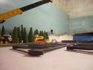
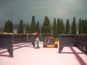
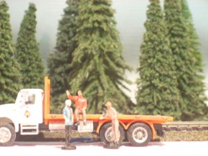
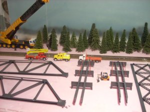
Here are some pics from the building yard where the bridge is being built before being put into place. There is a pic of the crew taking a break near a truck.
Here are some pics from the building yard where the bridge is being built before being put into place. There is a pic of the crew taking a break near a truck.
Attachments
")
Very cool! By the way, I don't know if you still are trying to make supports for the bridge, but you can use lego building bricks to make a form for the piers as well. Wayne obviously created extremely nice and detailed ones, but legos can work quickly and plaster poured in them turns out just fine.
Hope this can help,
Ginns
Hope this can help,
Ginns