I am starting a new project using several "IRS on fire" buildings. Two separate buildings will be created by swamping around parts from (so-far) 4 of these kits.
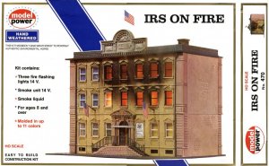
Two of the three other variants I know of are in the photo below.

The most common variant over here is the Model Power or IHC versions of the "IRS ON FIRE" building which comes complete with a smoke unit, smoke fluid and flickering red lights. I am not sure yet whether mine will be a "burning" building or not. Not one of my 4 buildings had any smoke fluid left -- all evaporated.
I've assembled the two shells (detail photos later on of the actual construction) to sort of see how I want to proceed. I have not yet decided to leave the buildings together or to put a small passageway between them. The left hand building is (at present) a 7-story skyscraper and the 3 story building on the right is made from 3 first storys of the 4 kits. I have enough parts to extend the left hand building to 9 stories if I wish.
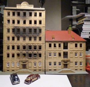
The two cars shown are custom painted Stony Mountain Packard automobiles
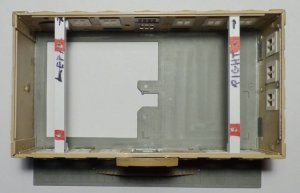
A short update on this project will show how I use the Machine Screws & Plastic Blocks to secure the floors together and to allow later access to the interiors. The first photo below shows the assembled shell of the first floor sitting on the base plate. Added were two cross beams of ¼” square rod of Evergreen plastic cut to a height of just under the lip along the walls which in the kit is to support the 2-3 floor walls. The “red” coloring shows the holes (drilled & tapped for 2-56 machine screws. The color is only for contrast to show this method of construction.
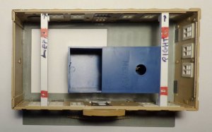
The next photo shows the smoke unit (dark blue box) sitting about where it would go if this were to be a burning building. This will NOT be used in this building. The third photo shows the floor which will hold the “burning portion” of the building if built as per kit instructions’ This building will also NOT use this piece but I used it as a template to cut two identical pieces of Evergreen plastic sheet about .04 thickness; these pieces will form the floors for story’s 2 & 3 of this building. The kit floor has some raised strips cast around the outside of the walls to raise the factory floor to the right place. Since I am using a flat piece of plastic I added in some shims to replicate the stock piece.
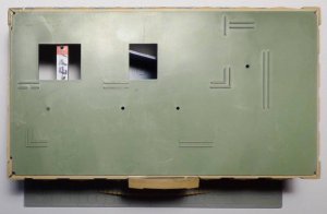
The new plastic floor for story 2 is then laid in place on story 1 and the walls assembled to it. Doing it this way usually keeps the building square (though that technique did not fully work on this building). I used plastic scrap rods and angle stock to secure the walls to the floor so as to not glue floor 2 to story 1 in the process. I now have a completed story 2 resting on story 1. After the glue dries enough to handle, I removed story 2 from the building and glued the walls to the floor 2 from the underside. This may seem to be overkill (as the sub floor is already glued together) but in the end it makes for a rigid sub structure that will stand up to handling in the process of any interior or lighting being installed.
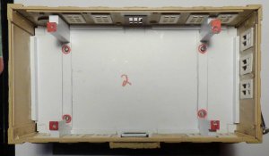
The photo above shows the ready floor 2 screwed into floor 1 with four 2-56 machine screws inside the red circles. The construction marks and red outlines will disappear when the interior is added but are left in to help illustrate the construction techniques and help me to remember what goes where during breaks in construction. A WORD OF CAUTION HERE: When using metal screws in plastic stock some care must be exercised when tightening them down. Unlike most metal to metal fastenings, you must use care not to over tighten them and strip out the threads in the plastic. Kadee (the coupler people) make a 2-56 threads per inch tap and die set at a reasonable price and all the block holes are threaded this way. The holes in the floor are drilled with a slightly larger clearance hole that the screw simply drops through. Tighten the screws until you see them hit the floor and feel resistance, then stop In a metal connection you would always add a partial turn to really snug the connection. You do not need to do that when tightening a screw in plastic. This small tap is quite brittle and can easily break if the tapping process is forced; even while drilling a ¼” tall block you will need to continually back the tap out and clear the flues of stuck on plastic. It’s a bit tedious to do this but it prolongs the life of your tap. Four ¼” square rods, braced against the walls are installed to allow floor 3 to be fastened eventually to floor 2; these are, again, cut to a height just under the lip around the walls at the top. Both the plastic blocks and machine screws are highlighted in red for clarity.
Story 3 walls are then assembled to floor 3 in the same manner as story 2. Scrap pieces of Evergreen plastic are used to attach the walls to the floor with out gluing Story 3 to Story 2 permanently by accident at this point. After the glue dries enough to handle Story 3 gently remove it from the building shell and glue the walls to the floor from the underside to add strength and rigidity to the sub structure.
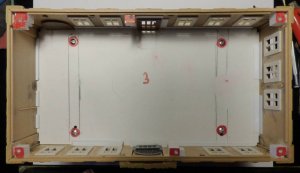
Four plastic blocks at the corners of Story 3 were used to test fit the flat green sub-roof to the floor. There was still a slight warp in the middle so two more blocks were added for a total of 6. These were drilled & tapped. The fourth photo below shows story 3 screwed to story 2 with 4 machine screws (outlined in red); and, the six blocks at the top in red that will allow the flat sub roof to be screwed into place.
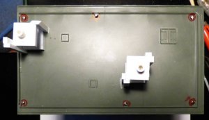
Next I assembled the slanted tile roof and test fitted it to the flat sub-roof. I could have used about 5 hands to help this keep the proper shape until the roof dried. Angle bits of scrap plastic were used to stiffen the roof. I got ahead of myself and glued the assembled chimneys to the roof (making it harder to put screws in them later on. A small piece of tubing was drilled out to clear the machine screw; a cone shape bevel was done on one end of the tubing to guide the screw into the hole in the chimney mount. The next photo shows the flat roof screwed on to the building shell with 6 machine screws. The strange white structures on the flat sub-roof are to guide the chimney screws into the threaded blocks to secure the slanted tile roof to the flat sub-roof making a completed shell. This job was a lot harder and resulted in these Rube Goldberg adapters because I got in a hurry and put the chimneys on first. After many trial fittings and filing and cutting the roof support structures in various places, I got the slanted tile roof to fit on flat sub-roof, etc. The threaded blocks are about 1” square to allow plenty of leeway when drilling a hole in them via a long drill down through the chimneys. Actually it isn’t that hard as I took a rounded toothpick, squared off one end, painted this with black marker, inserted it down through the chimney until it hit the block. Then it was easy to drill a correctly positioned hole through the block and then thread it. A small bit of tube drilled out a bit on one end was again used to guide the long screw from the chimney to the threaded hole in the block. Had I not put those chimneys in place for early I probably could have had a much simpler way of attaching the main roof to the sub roof.
The photo below shows the flat sub-roof as attached to the building shell; the six screws are outlined in red which doesn’t show too well against the dark olive green of the sub-roof. The Rube Goldberg adapters look like they belong in a sci-fi wargammer’s city somewhere.
And lastly, a photo of the front of the building showing some work I did on the front façade using the fancy trim of the front door cut down to fit the height of each story. Parts of the flat roof coping trim were cut to fit the door openings and a window piece not used in this bash fitted into the opening.
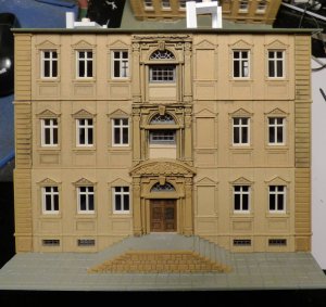
More to follow on this project; but, this gives you an idea on how to use machine screw & plastic block construction on a commercial kit. To avoid damage with all the handling no interior was made yet; the windows are small but a simple interior will be fitted and some lights installed. Remember, this won’t be a burning building so there will be no smoke unit or flickering red lights.

Two of the three other variants I know of are in the photo below.

The most common variant over here is the Model Power or IHC versions of the "IRS ON FIRE" building which comes complete with a smoke unit, smoke fluid and flickering red lights. I am not sure yet whether mine will be a "burning" building or not. Not one of my 4 buildings had any smoke fluid left -- all evaporated.
I've assembled the two shells (detail photos later on of the actual construction) to sort of see how I want to proceed. I have not yet decided to leave the buildings together or to put a small passageway between them. The left hand building is (at present) a 7-story skyscraper and the 3 story building on the right is made from 3 first storys of the 4 kits. I have enough parts to extend the left hand building to 9 stories if I wish.

The two cars shown are custom painted Stony Mountain Packard automobiles
A short update on this project will show how I use the Machine Screws & Plastic Blocks to secure the floors together and to allow later access to the interiors. The first photo below shows the assembled shell of the first floor sitting on the base plate. Added were two cross beams of ¼” square rod of Evergreen plastic cut to a height of just under the lip along the walls which in the kit is to support the 2-3 floor walls. The “red” coloring shows the holes (drilled & tapped for 2-56 machine screws. The color is only for contrast to show this method of construction.

The next photo shows the smoke unit (dark blue box) sitting about where it would go if this were to be a burning building. This will NOT be used in this building. The third photo shows the floor which will hold the “burning portion” of the building if built as per kit instructions’ This building will also NOT use this piece but I used it as a template to cut two identical pieces of Evergreen plastic sheet about .04 thickness; these pieces will form the floors for story’s 2 & 3 of this building. The kit floor has some raised strips cast around the outside of the walls to raise the factory floor to the right place. Since I am using a flat piece of plastic I added in some shims to replicate the stock piece.


The new plastic floor for story 2 is then laid in place on story 1 and the walls assembled to it. Doing it this way usually keeps the building square (though that technique did not fully work on this building). I used plastic scrap rods and angle stock to secure the walls to the floor so as to not glue floor 2 to story 1 in the process. I now have a completed story 2 resting on story 1. After the glue dries enough to handle, I removed story 2 from the building and glued the walls to the floor 2 from the underside. This may seem to be overkill (as the sub floor is already glued together) but in the end it makes for a rigid sub structure that will stand up to handling in the process of any interior or lighting being installed.

The photo above shows the ready floor 2 screwed into floor 1 with four 2-56 machine screws inside the red circles. The construction marks and red outlines will disappear when the interior is added but are left in to help illustrate the construction techniques and help me to remember what goes where during breaks in construction. A WORD OF CAUTION HERE: When using metal screws in plastic stock some care must be exercised when tightening them down. Unlike most metal to metal fastenings, you must use care not to over tighten them and strip out the threads in the plastic. Kadee (the coupler people) make a 2-56 threads per inch tap and die set at a reasonable price and all the block holes are threaded this way. The holes in the floor are drilled with a slightly larger clearance hole that the screw simply drops through. Tighten the screws until you see them hit the floor and feel resistance, then stop In a metal connection you would always add a partial turn to really snug the connection. You do not need to do that when tightening a screw in plastic. This small tap is quite brittle and can easily break if the tapping process is forced; even while drilling a ¼” tall block you will need to continually back the tap out and clear the flues of stuck on plastic. It’s a bit tedious to do this but it prolongs the life of your tap. Four ¼” square rods, braced against the walls are installed to allow floor 3 to be fastened eventually to floor 2; these are, again, cut to a height just under the lip around the walls at the top. Both the plastic blocks and machine screws are highlighted in red for clarity.
Story 3 walls are then assembled to floor 3 in the same manner as story 2. Scrap pieces of Evergreen plastic are used to attach the walls to the floor with out gluing Story 3 to Story 2 permanently by accident at this point. After the glue dries enough to handle Story 3 gently remove it from the building shell and glue the walls to the floor from the underside to add strength and rigidity to the sub structure.
Four plastic blocks at the corners of Story 3 were used to test fit the flat green sub-roof to the floor. There was still a slight warp in the middle so two more blocks were added for a total of 6. These were drilled & tapped. The fourth photo below shows story 3 screwed to story 2 with 4 machine screws (outlined in red); and, the six blocks at the top in red that will allow the flat sub roof to be screwed into place.

Next I assembled the slanted tile roof and test fitted it to the flat sub-roof. I could have used about 5 hands to help this keep the proper shape until the roof dried. Angle bits of scrap plastic were used to stiffen the roof. I got ahead of myself and glued the assembled chimneys to the roof (making it harder to put screws in them later on. A small piece of tubing was drilled out to clear the machine screw; a cone shape bevel was done on one end of the tubing to guide the screw into the hole in the chimney mount. The next photo shows the flat roof screwed on to the building shell with 6 machine screws. The strange white structures on the flat sub-roof are to guide the chimney screws into the threaded blocks to secure the slanted tile roof to the flat sub-roof making a completed shell. This job was a lot harder and resulted in these Rube Goldberg adapters because I got in a hurry and put the chimneys on first. After many trial fittings and filing and cutting the roof support structures in various places, I got the slanted tile roof to fit on flat sub-roof, etc. The threaded blocks are about 1” square to allow plenty of leeway when drilling a hole in them via a long drill down through the chimneys. Actually it isn’t that hard as I took a rounded toothpick, squared off one end, painted this with black marker, inserted it down through the chimney until it hit the block. Then it was easy to drill a correctly positioned hole through the block and then thread it. A small bit of tube drilled out a bit on one end was again used to guide the long screw from the chimney to the threaded hole in the block. Had I not put those chimneys in place for early I probably could have had a much simpler way of attaching the main roof to the sub roof.
The photo below shows the flat sub-roof as attached to the building shell; the six screws are outlined in red which doesn’t show too well against the dark olive green of the sub-roof. The Rube Goldberg adapters look like they belong in a sci-fi wargammer’s city somewhere.

And lastly, a photo of the front of the building showing some work I did on the front façade using the fancy trim of the front door cut down to fit the height of each story. Parts of the flat roof coping trim were cut to fit the door openings and a window piece not used in this bash fitted into the opening.

More to follow on this project; but, this gives you an idea on how to use machine screw & plastic block construction on a commercial kit. To avoid damage with all the handling no interior was made yet; the windows are small but a simple interior will be fitted and some lights installed. Remember, this won’t be a burning building so there will be no smoke unit or flickering red lights.
Last edited:

