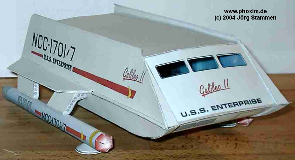
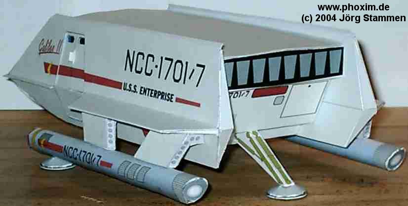
I was afraid I might catch up on my builds, so I started another one to keep things normal. This is my build of the Galileo shuttlecraft model created by Joerg Stammen in 2004. This is one of the first models I ever downloaded and it has been sitting in my computer for a while. That’s a good thing because while it’s a nice model it falls short of accurate in a lot of areas. I think I’ve got the experience now to make her better.
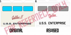
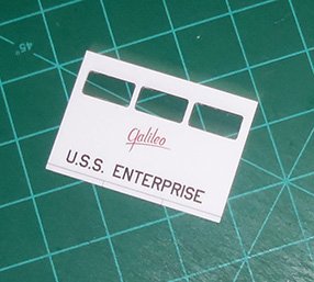
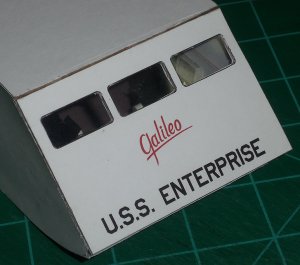
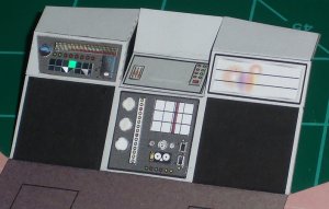
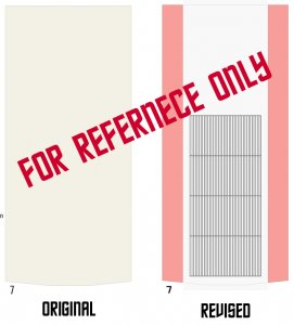
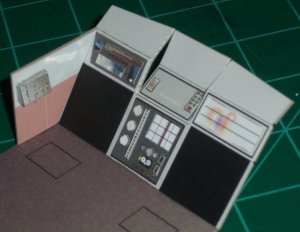
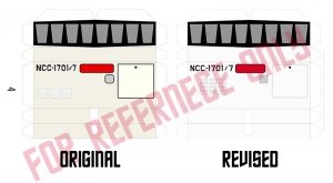
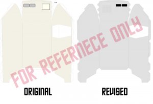
Most Trekkers and Trekkies know there are a lot of conflicts with the look and size of the Galileo. The interior set doesn’t fit in the full-size prop and the interior changed from episode to episode. My goal was to get the model as close as possible to what was on screen at any given time. Changes to the design will be listed in each section. Some overall changes include changing hull colors to light and dark grays to better match the studio model and remaking all hull registries with correct fonts and positioning. I also changed her to the Galileo instead of the Galileo II. That alone made a big change to the model.
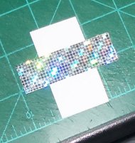
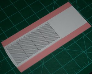
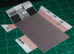
As with all my models, all parts are scored and edge colored as needed.
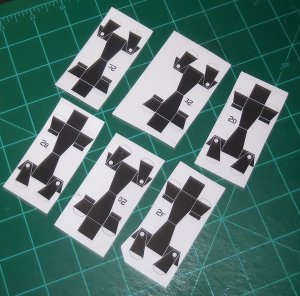
CHAIRS
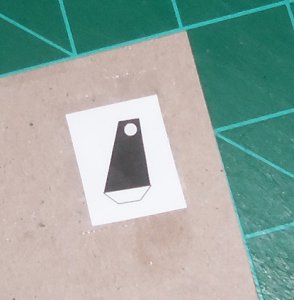
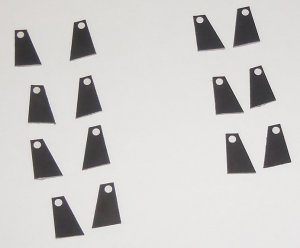
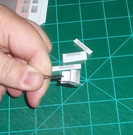
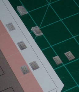
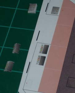
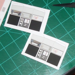
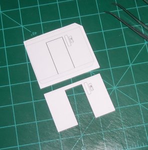
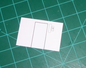
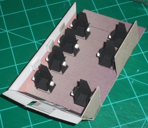
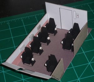
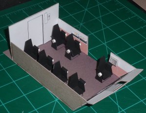
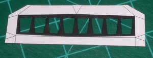
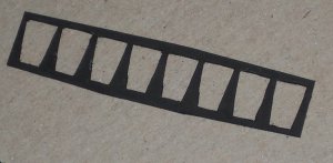
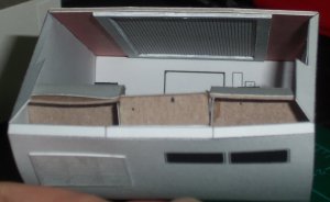
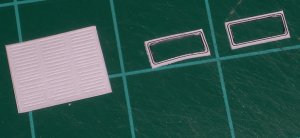
The chairs in the Galileo were molded black plastic chairs that swiveled and tilted. They mounted to the floor with a U-shaped base. I didn’t have the skills to rework the original chairs in any significant way so I kept the original design.
I used double-sided tape on the back and seat section. Glue makes the parts too wavy. The tape allows the part to have some give when folding. However, sometimes the tape wasn’t strong enough to keep the parts together. When it came apart then I used a little Super Glue gel to hold the edges together. I went over all the white lines with a black Sharpie to make the chairs solid black.
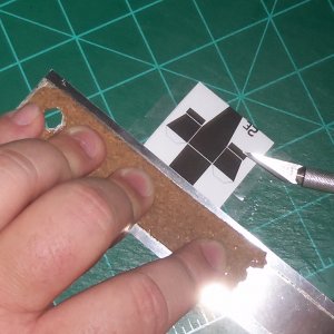
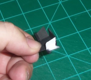
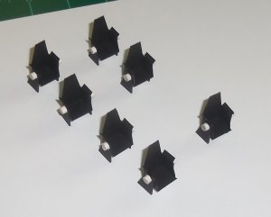
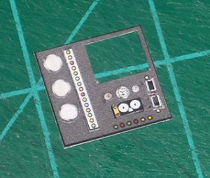
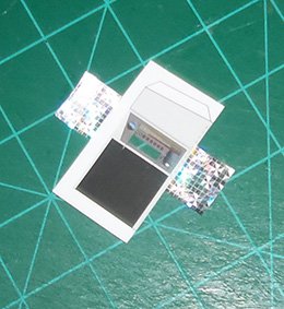
I made the chairs sturdier by mounting the legs to 1mm chipboard. I colored them all black and mounted them to the seats. I could still faintly see where the original white lines for the legs were, so I used those to align them for gluing. To replicate the seat adjustment knobs I cut sections out of lollipop sticks and glued them over the white circles on the legs.
Most Trekkers and Trekkies know there are a lot of conflicts with the look and size of the Galileo. The interior set doesn’t fit in the full-size prop and the interior changed from episode to episode. My goal was to get the model as close as possible to what was on screen at any given time. Changes to the design will be listed in each section. Some overall changes include changing hull colors to light and dark grays to better match the studio model and remaking all hull registries with correct fonts and positioning. I also changed her to the Galileo instead of the Galileo II. That alone made a big change to the model.
As with all my models, all parts are scored and edge colored as needed.
CHAIRS
The chairs in the Galileo were molded black plastic chairs that swiveled and tilted. They mounted to the floor with a U-shaped base. I didn’t have the skills to rework the original chairs in any significant way so I kept the original design.
I used double-sided tape on the back and seat section. Glue makes the parts too wavy. The tape allows the part to have some give when folding. However, sometimes the tape wasn’t strong enough to keep the parts together. When it came apart then I used a little Super Glue gel to hold the edges together. I went over all the white lines with a black Sharpie to make the chairs solid black.
I made the chairs sturdier by mounting the legs to 1mm chipboard. I colored them all black and mounted them to the seats. I could still faintly see where the original white lines for the legs were, so I used those to align them for gluing. To replicate the seat adjustment knobs I cut sections out of lollipop sticks and glued them over the white circles on the legs.


 rinks:
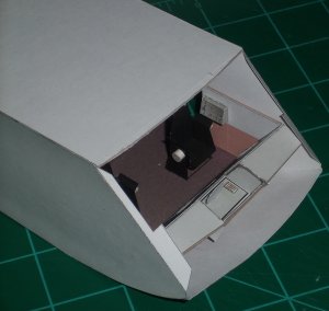
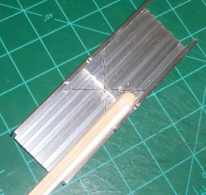
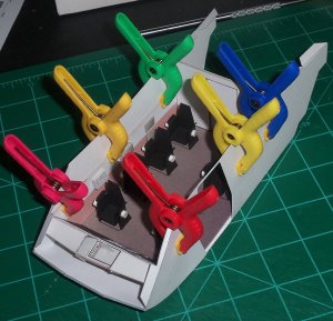
") I've got more updates to post and I already did exactly what you suggest, I built all the walls separate and scratch built supports to make everything straighter on the exterior hull. My builds are so slow because I'm always trying to come up with supports/braces/frames that make the models straighter and stronger (like the ridiculous amount of support I built into my Enterprise-C, that thing is heavy!:happy
I've got more updates to post and I already did exactly what you suggest, I built all the walls separate and scratch built supports to make everything straighter on the exterior hull. My builds are so slow because I'm always trying to come up with supports/braces/frames that make the models straighter and stronger (like the ridiculous amount of support I built into my Enterprise-C, that thing is heavy!:happy") . And I definitely won't be using those petal bussards! I hate that design and it always looks like crap! I'll either use yours or ones like it.
. And I definitely won't be using those petal bussards! I hate that design and it always looks like crap! I'll either use yours or ones like it.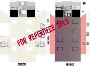


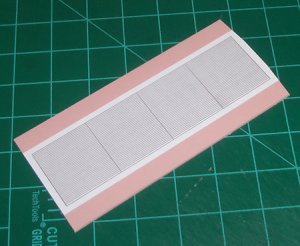
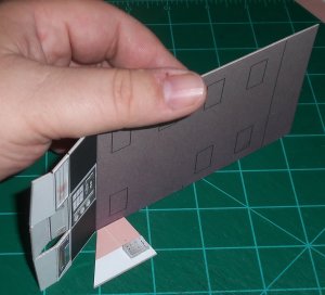
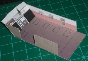
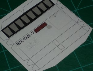
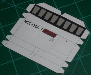
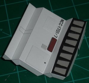
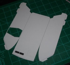
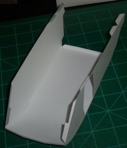

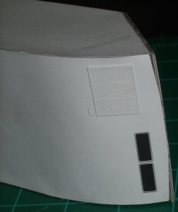
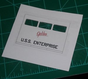
 With the front on an angle the outside edges would have to be higher than the center to meet up with the roof and lower hull, which angles away in the other direction. In effect, the front would have to be “bow-tie” shaped.
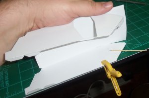
 Then I used Super Glue gel to lock the top and side edges into place.