Hi rschroots
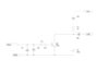
in this case there is an error on the drawing. The diode D3 must go on line lower on the PCB i.e. the cathode to the collector of the transistor.
Furthermore it will NOT work with Conrad module as it expects stady status on the diode output i.e. high when the block is empty and low when occupied. as in the track there is no DC voltage, DCC is alternating by about 4-5 kHz (4000-5000 times per second) the output of the Q1 will exactly follow the positive part of the DCC shape, and the Conrad module will not recognize the status. You need to add the capacitor also to the Q1 Collector and to the GND to remove the high frequency componets from the signal.
Try and and you will see what is the reaction.