Hi everybody.
There are few confusions.
a.
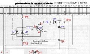
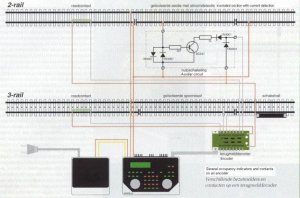
The circuit will work on DCC when the basic conditions for the transistor circuitry are given, i.e. it has the correct polarity. (Emitter negative, collector positive).
You cannot simple swap the polarity.
b.
The circuit will indicate the occupancy only during the positive voltage period of the DCC circuit (the antiparallel diode on the front has nothing to do with it, it blocks only the negative voltage from the basis out, the transistor will switch only to positive polarity on the input).
c.
With voltmeter it is very difficult to measure, because the output of the circuit has the same pulses as the DCC what you will not see on any commercial voltmeter (they are to slow).
d. the output stage is a bad design, probably a mistake on the drawing. The real output is not on the common point of the diode and the resistor, see later.
d.
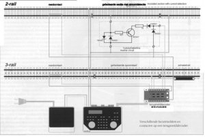
I do not know exactly the function of the following encoder (probably a factory made box). For that reason the analysis is for me extremely difficult. I simple cannot believe that they are going to analyse the jumping (with DCC frequency) output of the transistor, i.e. the occupancy detector in dynamic mode with the same frequency as the DCC is. This would be very bad from many different points of view....
e.
The circuitry is far too simple for reliable work. (probably it was made by a designer, who never had a train under the Xmas tree.
f.
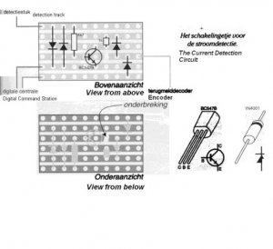
To indicate the function of the detector I would replace at least in this stage one of the output diodes D4 with a RED LED, which will lit when the Q1 switches (does not matter of the DCC frequency).
My suggestions:
1. Any "normal" occupancy detector must have some kind of decay. The model train is not that reliable, that the current is always there. This circuitry in such case will indicate the train in the next moment will not. To avoid this you have to add a bigger capacitor (tantal at least 50uF/20V, + leg to the C of the Q1, - leg to TP2) to the output. This will change also the function of the circuit and will switch continuosly to zero voltage when the block is occupied (you can measure it with voltmeter). And remains switched for a while also after the train leaves - I prefer about 1 second. This gives you a reliability for poor contact and detects also cars with resistors between the wheels.
2. The output is a bad design. The output must be the point where the collector C the Q1 is connected to the R2. I.e. the D3 cathode must be wired to this point, the D4 cathode to the end of the resistor R2.
3. Probably a single diode on the input (D1 and D2) is not enough to switch the transistors - the basis usually requires about 0.7V to switch on the most modernSi diodes you can get in forward biased mode something about 0.6V. In a more professional design there are two diodes in series instead of a single D1 and one in oposite direction (D2), which gives about 1.2 V on the input when occupied. This is more then enough to switch the Q1.
4. For a much more better design with OPAMPs you can use only similar two diodes as in this circuitry, (and you will really detect in both direction), but this is much more complex circuitry (see MR about 2 years ago).
Good luck, and never trust such simple circuitry (7 components, and how many problems)....
B]model railroad is more serious then many electronic designers ever dreamed about.[/B]

:curse: :thumb:[


")

")