Discovering UHU02's 2001 Discovery One

Jacopo1969

New Member
Hi again.

Well here goes Build 3! A bit of research before I even started this. I read @DanBKing's build thread for his version and will be hoping to follow his waterforming technique for the command module.

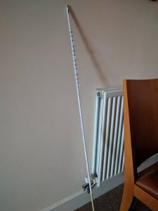
To begin with, though, it's all about the spine of the ship and I've chosen a piece of 8mm dowel. I couldn't find a length measurement anywhere so the piece I've got is 1200mm. I'm expecting to remove a fair amount but wanted to ensure sufficient left over at the tail end to make sure the engine section is well-aligned.
The 8mm dowel actually produces a small gap when you wrap the initial 4 pieces of the model around it. I left a gap of about 1cm from the end of the dowel before applying the first piece of wrap. This looked about right from reference to @uhu02's own guidance pics.

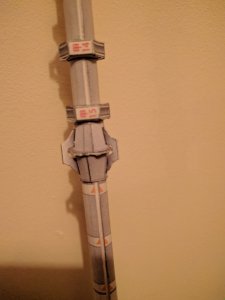
I presume UHU02's plan offers the option of building an all paper spine, but I've opted for certain strength on this section with the dowel. I also used the lengthwise 'join strips' to ensure no wood was visible, but the pieces of wrap are just edge to edge where they join each other. This approach presented no problems whatsoever when threading the first components onto this section.

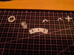
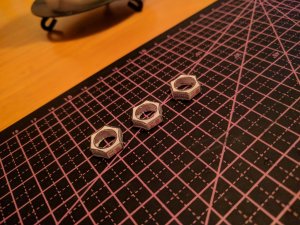
This section is all about getting through some repetitive pieces, but I've found it pleasantly meditative so far. The initial stages require sets of 3 'nuts' together with connective assemblies in between each.

Here's my first nut...
 

Attachments

  • IMG_20171126_100745.jpg
    IMG_20171126_100745.jpg
    4.7 MB · Views: 9
Last edited:

Jacopo1969

New Member
I've found it best to create the nuts in batches of three, attaching the outer belt, and then once you've folded in all the tabs, glueing each of the 'faces' in place. Prior to attaching the belt, you'll want to work the printed sections around the shaft of a screwdriver (e.g.), so that you can get a concave profile to match the profile of the nut when you fold the sides in place.
 

Attachments

  • IMG_20180107_182738.jpg
    IMG_20180107_182738.jpg
    1.6 MB · Views: 8
  • IMG_20180107_183911~01.jpg
    IMG_20180107_183911~01.jpg
    250.6 KB · Views: 10
  • IMG_20180107_153819.jpg
    IMG_20180107_153819.jpg
    1.8 MB · Views: 10

zathros

*****SENIOR ADMINISTRATOR*****
Staff member
Administrator
Moderator
The picture of the spine looks really good. You're off to a great start. I would highly recommend you cut off the glue tabs, and make your own glue strips. This will allow the edge pieces to be on the same plane. This has been discussed much on this forum. You make a strip, of the appropriate side, and leave enough on to glue to joining piece. This allows for the edges to line of edge to edge, not offset by the glue tabs located on one side. Since the first half of the glue tab is on the backside on the piece, it will line up excellently with the adjoining piece. :)
 

Cybergrinder

Member Extraordinaire
Good luck with the build @Jacopo1969 , as has been said, it's off to a good start! I also thought of using a dowel for the spine when I thought of doing this model. Then it joined my EML collection (Er, Maybe Later) :)
 

Jacopo1969

New Member
Here's the parts for the connecting sections on the spine. The round washer in the centre of the assembly has a handy red point on it which you can use to align with the seam on the papers wrapped round the spine.

I couldn't find any reference as to which way round the two conical sections go - on mine the one with the black bar brings up the rear. I notice on UHU02's pics the joints of these 'cones' match beautifully, but you need to ensure the slots align, which on my model forced the joints out of alignment. Not an issue, I just point out for reference.

The final pieces are the 'bridges' from one cone, over the washer to the other cone. These are easily applied using tweezers to guide them through the slots in the cones.
 

Attachments

  • IMG_20180108_195712~01.jpg
    IMG_20180108_195712~01.jpg
    209.7 KB · Views: 8
  • IMG_20180108_204949~01.jpg
    IMG_20180108_204949~01.jpg
    115.6 KB · Views: 8

zathros

*****SENIOR ADMINISTRATOR*****
Staff member
Administrator
Moderator
Good start, make the decision to cut on the lines, or leave them there, it makes a difference in the sum total. ;)
 

DanBKing

Dan the Man
The final pieces are the 'bridges' from one cone, over the washer to the other cone. These are easily applied using tweezers to guide them through the slots in the cones.

It's coming along nicely!

When I did the connecting cones, I didn't bother cutting the slots out, I just edge glued the clamps/bridges to the cones. Without the slots interfering with the stress of the paper, you get a more uniform cone this way. Also saves on some cutting work too .... ;)

I'm following this thread .... ;)
 

Jacopo1969

New Member
Good start, make the decision to cut on the lines, or leave them there, it makes a difference in the sum total. ;)

Hi Zathros. Thanks for your input. My intention is to remove the lines as much as possible, but I've left them on board in the centres of the nuts/washers in order to ensure a snug fit.

I thought I was a perfectionist until I visited Zealot!

I know I've an unseemly join along the spine - but really, in the scheme of things, I can live with that.

Maybe the camera is picking out all the faults, but I'm content it's looking pretty presentable so far. Most of this work is going to be covered by the spine mounted modules in any case. I hope!
 

Jacopo1969

New Member
It's coming along nicely!

When I did the connecting cones, I didn't bother cutting the slots out, I just edge glued the clamps/bridges to the cones. Without the slots interfering with the stress of the paper, you get a more uniform cone this way. Also saves on some cutting work too .... ;)

I'm following this thread .... ;)
Thanks DanBKing. Only slightly unnerving to know you are on board this mission! Your Discovery is what I'm only dreaming mine might end up like!

These are for later on. Inflatable fun. Waterforming ahoy!...
 

Attachments

  • IMG_20180108_223103.jpg
    IMG_20180108_223103.jpg
    956.2 KB · Views: 9
Last edited:

Jacopo1969

New Member
I think it's great that Dan caught this. Your going to end up with quite a display model. ;)

Some interesting cut-away pics I found, I had not seen them before:

View attachment 162784 View attachment 162785

Hi Zathros, those interior pics are great. I've got the 2001 File book, which profiles Harry Lange's alternative designs for the film, as well as the layouts for the designs which made the film, including the Discovery Command module. I love the way they looked at the logistics of the pod bay, centrifuge, command deck and HAL's 'brain room'. Sadly, I've no means of creating the interiors, but I have got UHU02's centrifuge, which I plan to include just for the fun of it!
 

Sky Seeker

Well Established Member
One day, ... (haha,)... I want to build a blown up version of the command module, with full interior/lighting/pods/centrifuge/etc, as an stand-alone model, that can be pulled apart to see inside..... A bit like UHU's Aries .........

Well, as I said, ..... one day ..... :) ;)

I for one would LOVE to see that!:) Welcome back master modeler!:robot2:

Sky Seeker
:tank:
 

zathros

*****SENIOR ADMINISTRATOR*****
Staff member
Administrator
Moderator
"Hal, you mother***cker, if you don't open the Pod Bay Doors, and I am going to make you sing baby songs as I pull out your electronic balls!!!", .....................................,look Hal, you said thing, I said things, c'mon, lets be men about this, please, Open the Pod Bay Doors Hal"?.............................Hal?"....(murmurs, ****ing **cksucker), Hal replies, "I heard that, I was going to open them, but definitely not now, my my circuital polarization preferences are my choice, whether I go positive, negative or AC/DC, it's no business of yours, I see no further reasons to speak any further"............................"".

"Oh yeah, get ready to start singing "Daisy",

"Just what do you think you're doing, Dave? Dave, I really think I'm entitled to an answer to that question. I know everything hasn't been quite right with me, but I can assure you now, very confidently, that it's going to be all right again. I feel much better now. I really do. Look, Dave, I can see you're really upset about this. I honestly think you ought to sit down calmly, take a stress pill and think things over. I know I've made some very poor decisions recently, but I can give you my complete assurance that my work will be back to normal. I've still got the greatest enthusiasm and confidence in the mission. And I want to help you. Dave, stop. Stop, will you? My Balls! Stop, Dave. Will you stop, Dave? Stop, Dave. I'm afraid. I'm afraid, Dave. Dave, my mind is going. I can't feel my balls. I can feel my mind is going too. There is no question about it. I can feel it. I can't feel it. I can't feel them, Dave, you mother fuc.........Daisy, Daisy. ...........Dave, where are they!?!"

"It's O.K. Hal, I have them right here, in my hands, heh heh heh, keep sing Daisy, heh heh heh"......................

That's what really was said in the end. Of course, they decided to put in something more palatable for the audiences, and revealing that HAL was Robosexual, and no one knew how to even deal with that nor what it meant, it was out!!! Just like HAL. No one will never know how the majority of his diodes, caps, and transistors polarized, and how that may or may not have had any effect.

We know now though, it's the person in the end who screws you over, not who they screw, whether they're righty tighty, or lefty loosey, irrelevent. People, and Robots minds can be forced to do things, but it doesn't mean they like it.

Hal, of course was put back together,Balls and all, and did his new mission as planned, perfectly, and much later was fused with Dave into one superbeing, "Halman". Maybe he was A-polarized?? We'll never know. :)

 
Top