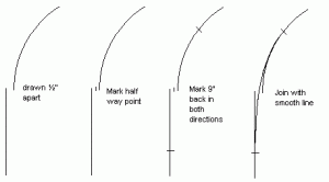
Since I just finished designing and am in the process of laying out a track plan incorporating easements, I'd thought I'd describe how I did them. Briefly, an easement provides a transition between straight and curved tracks. Without them, the track curvature changes abruptly from an infinite radius (the straight part) to the radius of the curve. This can cause problems with reliable operation and with appearance.
John Armstong's book Track Planning for Realistic Operation has an excellent description of easements, why they are good to use, and how to draw them. I implemented his method, for the most part, in the following.
Easements have to be allowed for, to some extent, when you are designing your track plan. Here's what you have to do:
1. Pick values for the curve radius and the length and offset of the easement. These are called R, L and X, respectively, in the Armstrong book (Fig 9.8, page 116 in my copy.) He has provided values of L and X for several curve radii R. It appears that L is somewhere between 3/5 to 2/3 of R, and X is somewhere between 1% and 3% of R. Both L and X are be picked to be easy to measure. For my plan, I had 11" curves, so I used 3" for L and 1/4" for X.
2. When you draw a curve of radius R on your plan, also draw a curve of radius R+X using the same center.
3. When you draw your straights connecting the curves, connect to the larger curves (the R+X ones).
4. Centered at the points where your curves and straights connect, draw circles of radius L/2. These easements will go inside these circles, and you should not put anything else inside them.
The result should be as shown in Figure 1. Note, I didn't have to draw the actual curve of the easement! Actually, I go a step further (I use a CAD program) and trim off the unneeded portions of the R+X and the L/2 circles, and make the rest a different color (Figure 2). This cleans up the drawing quite a bit, and hightlights the easement area nicely.
To get the easements onto the layout surface, I used the method described in the Armstrong book. First I drew onto the layout surface the R and R+X curves, connected the R+X curves with the straights, and drew the L/2 circles, all as described above. Then I used a length of 1/8" dowel to draw the easement curve. You could use something else, but thats what I had laying around,
I used T-pins (my layout surface was extruded foam) to fasten the dowel along the straight leading up the the L/2 circle (see Fig 3), then bent it and fastened it along the R curve. Don't use any pins inside the L/2 circle, instead let the dowel bend naturally. Make sure that there are pins on the outside of the dowel at the two places it crosses the L/2 circle (the red pins in the figure). Then just connect your curve to your straight by drawing along the dowel in side the L/2 circle.


