To: N Gauger - Mikey, unless you are dead bent on useing leds. Give this one a try. It worked really well for me. I have built several and use them for tower lighting, street and house lighting, even auto turn signals. :thumb:
[size=+2]Functional description[/size]
[size=+1]The module turns on or off eight different lights (or groups of lights) in a pre-programmed sequence. The sequence is started with a pulse from e.g. a k83 decoder or a manual push-button. The first pulse starts an "on" sequence, the second an "off" sequence and so on. The module has four different programs, selectable via jumpers. Each program has separate "on" and "off" sequences.[/size]
[size=+2]Building and programming the module[/size]
[size=+1]I built the module on a Veroboard. I do not think it is worth the effort to make a real circuit bord for just one or a few units. The design is based on a PIC processor, the PIC16C505. The program I developed for Peter Funck's module can be found here:[/size]
[size=+1]The sequences in this program are:[/size][size=+1][/size]
[size=+1] Sequence 0 (RB5 and RB4 low). Total 20 s:[/size]
[size=+1] [/size]
[size=+1] On: L0 (5s) L1 (2s) L2 (4s) L3 (1s) L4 (3s) L5 (4s) L6 (1s) L7[/size]
[size=+1] Off: L4 (2s) L2 (5s) L6 (3s) L1 (2s) L7 (1s) L0 (5s) L5 (2s) L3[/size]
[size=+1] [/size]
[size=+1] Sequence 1 (RB5 low, RB4 high). Total 11 s on, 13 s off:[/size]
[size=+1] [/size]
[size=+1] On: L0 (2s) L1 (1s) L2 (2s) L3 (1s) L4 (2s) L5 (2s) L6 (1s) L7[/size]
[size=+1] Off: L4 (1s) L2 (3s) L6 (3s) L1 (1s) L7 (1s) L0 (3s) L5 (1s) L3[/size]
[size=+1] [/size]
[size=+1] Sequence 2 (RB5 high, RB4 low). Total 20 s:[/size]
[size=+1] [/size]
[size=+1] On: L4 (2s) L2 (5s) L6 (3s) L1 (2s) L7 (1s) L0 (5s) L5 (2s) L3[/size]
[size=+1] Off: L0 (5s) L1 (2s) L2 (4s) L3 (1s) L4 (3s) L5 (4s) L6 (1s) L7[/size]
[size=+1] [/size]
[size=+1] Sequence 3 (RB5 and RB4 high). Total 13 s on, 11 s off:[/size]
[size=+1] [/size]
[size=+1] On: L4 (1s) L2 (3s) L6 (3s) L1 (1s) L7 (1s) L0 (3s) L5 (1s) L3[/size]
[size=+1] Off: L0 (2s) L1 (1s) L2 (2s) L3 (1s) L4 (2s) L5 (2s) L6 (1s) L7[/size]
[size=+1] [/size]
[size=+1]If you are familiar with PIC programming you can change the sequences in the source code, assemble it and get a new .hex file. To simplify the programming for those who are not familiar with PIC processors, I have written a DOS program
hexgen.exe that generates a .hex file based on input from the keybord or from a text file.[/size][size=+1][/size]
[size=+2]Power supply[/size]
[size=+1]Power is supplied via the yellow and brown wire, see below. The module can operate with 10 - 20 V AC or DC.[/size]
[size=+1]Note that the power supply must be isolated from other equipment on the layout![/size]
[size=+2]Control[/size]
[size=+1]A program sequence is started by a voltage pulse on the control inputs, blue and yellow wires, see below.[/size]
[size=+1]Blue is + and yellow is -. The voltage of the pulse should be 5-30 V and the duration minimum 20 ms.[/size]
[size=+2]Output[/size]
[size=+1]There are four 3-pole flat cable outputs, each carrying two outputs. The outputs are the outer wires, and the[/size]
[size=+1]center wire is a common return wire. The return wire is the positive end.[/size]
[size=+1]Each output can be loaded with 0.5 A at 25 C (derate with 4 mA/C at temperatures over 25 C).[/size]
[size=+1]The total load on all 8 outputs together must not exceed 3 A.[/size]
[size=+2]Program select[/size]
[size=+1]Four different programs can be selected via jumpers on two pin headers, see below.[/size]
[size=+2]Schematic:[/size]
[size=+2]Component placement and connections:[/size]
[size=+1]Seen from solder side.[/size]
Copy this and and place in word and then resize the drawings. Lots of luck,
rcline - little choo choo
")


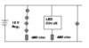
 It's a regulated power supply - it actually "Adjusts" to voltage & current. The more "Junk" you add on to it - it adjusts the output Voltage to 12V
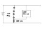

 :curse:


