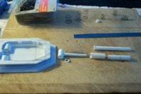
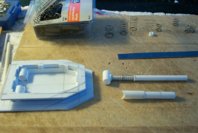
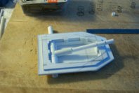
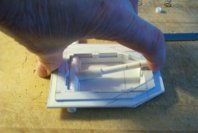
Blackadder's Scratchbuilt Thunderhawk Redux

Blackadder

Well-Known Member
He's Back!

Now to begin again I've decided to post my goal, namely a 3D rendering of the most realistic Thunderhawk I've yet seen and then show where I am in this replication-wise

First the 3D rendering:

ThunderhawkAction00000.jpg

This I believe is the model for a movie short and it employs almost all the features of the FW resin model less the nose and wing bolters. I shall be installing these on my model but as removable capability for alternate weaponry. I also added a pair of ball turrets ala Storm Raven because my Thunderhawk is so much larger than the FW model.

Next slide please:

ThunderhawkAction00001.jpg

This rear view had me very excited when I first saw it as it was as if the artist was looking over my shoulder when I was building the engine exhausts. My 'hawk has LED lighting that simulates the glowing afterburner cones almost exactly.

So now that we've seen the goal; the next post will show how close I've been able to approximate it.
 

Blackadder

Well-Known Member
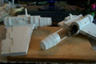
First the exhausts because I completed them in September of 2013:

Serendipity Reared its Ugly Head

Don't hate me because I'm lucky.

Back when I was building the engines in order to bulk up the adjacent wing surfaces I applied box beams to either side of the engines. I had forgotten about them so when I cut into the ends of the engine cowl I found these ready made receptacles for removable stringers attached to the exhaust cones.

6kchHzJ.jpg

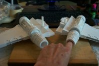
A little care in aligning the plug in stringers and there are plug in exhaust components so access to the battery operated LED lighting.

By pressing on the lens of the flashlight activates the pushbutton switch at the base of the light allowing it to be turned on and off without removal.

2siqcih.jpg

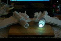
Now it only remains to colour the cones to glow superheated when the light is activated to simulate afterburners.
1VFha00.jpg
 

Blackadder

Well-Known Member
If I had my choice I would sooner be building a 'Marauder' which is IMHO the best looking aircraft in the Imp. Navy just as the B-25 and B-26 were the coolest Bombers in WWII, again IMHO.

I can't wait to finish up some of these projects to start on a Marauder.

Pause and Reflect:

Time to step back and see where we are proportion-wise.

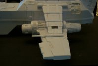
Mounting the Flying Lascannons struts shows me I must extend the wing roots about 13 MM which will increase the wingspan about one inch. The Lascannon length is okay so that can be detailed today.

struts 1.jpg

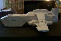
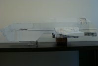
The overall length of the T'hawk is 26 inches, 7 inches longer than the FW version and I am hard pressed to find a place to photograph the entire model.

struts 2.jpg

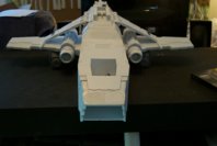
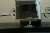
Likewise the front view; with the struts in the stowed position it looks very much like the 3D image but we can do better than that as I believe FW added the laser struts to keep the resin models wings from drooping. My model has a 7,0millimeter aluminum rod that keeps the wings level even with out the laser cannon struts so.......

struts 3.jpg

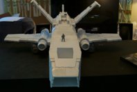
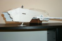
.........with the struts deployed it has a decidedly menacing appeal.

struts 4.jpg

This model is starting to grow on me; mebbe I should work on it more often.
 
Last edited:

Blackadder

Well-Known Member
Thanks for the reply,

RETRACTABLE NOSE LANDING GEAR:

One of the most fun thing about scratch building is trying to make a poor design workable. There is not enough space in the FW Thunderhawk to encompass the amount of structure and mechanics that would be necessary for an actually working aircraft. Even my outsized model I am hard pressed to make room for a viable and believable transport never the less...........

Started on the nose gear retractable landing gear today. I want a fully movable gear that retracts and extends and there is a very limited space between the gear bay and the floor of the cargo bay. The big issue is the collapsible oleo strut which acts as a shock absorber when the aircraft lands. I lost a couple of hours sleep the past few nights coming up with a workable design.

We'll see how it works out.........................

The first part is easy since the belly of the aircraft show a reinforcing plate around the nose gear well....

01.jpg

I next determined the available space between the plate and the interior flooring which appeared to be about a half an inch 0r 13 millimeters......02.jpg

03.jpg

I then added a ceiling to my gear well which gave me the available space within which to design my retractable gear....

04.jpg

Without going into all the trial and error I'll show what I ultimately came up with with the retract gimbals in the rear and the mount reinforcements forward
05.jpg

Now we can design the oleo strut and hydraulic retract cylinders.
 

zathros

*****SENIOR ADMINISTRATOR*****
Staff member
Administrator
Moderator
Is this PVC you using? It's impressive you are getting these kind of details. I only know of one other person and he built ships for ship companies, they were as big as canoes! I imagine you have some power tools, or the arms and fingers of Hercules!! I would like to know you bonding agent in you didn't mind. I just used the stuff from Home Depot, and wondered if much had changed. ;)

p.s. Sometimes I wish our like button had levels of like to it. ;)
 

Blackadder

Well-Known Member
Thanks for the reply, I use to build wooden ship models my myself but nothing as large as you are describing. I worked 1/96 scale; 1/8 inch equals a foot which is a tad small for a Wood plank on frame sailing ship. My best work was the USF Constitution "Old Ironsides" complete with masts and sails but I find rigging tedious so I don't build sailing ships anymore.

Most of your questions I can answer below but I have to find an image of the tools I use but I can tell you I rarely use power tools because of the heat sensitively of the plastic.

Materials:

I've seen styrene foam, cardboard, Foam filled posterboard, wood, plastic paneling, & etc. used and I made the mistake of using foam filled posterboard on two of my constructs; the Warhound Lucie and the Thunderhawk and I have to relate I have always regretted not using styrene sheets throughout the construction.

The problem is getting everything to hold together, the different materials require different glues which usually are incompatible with the other surfaces. You spend more time, effort, cost of resins and epoxies plus hours of drying time and sticky residue on everything including fingers, clothing, furniture, computer keyboards, and whatnot than it would be to just bite the bullet, and spend a few more bucks and go full styrene for the whole project. I purchase my sheet styrene from commercial plastic wholesalers usually found in most industrial parks. I buy small 3 foot X 6 foot sheets for about 16 bucks each in 3 thicknesses 0.020, 0.030 and 0.040 because that's what my local supply stocks and they're only a half hour round trip from me. I purchase about three sheets a year give or take.

I find it more economical to not use thicker styrene 0.060 and 0.080 except in special areas where excessive strength is required because it's too hard to cut with your standard utility knife and it's about 3 times more expensive than 2 sheets of thinner styrene sandwiched together but that's your choice.

As a point of fact I only used 2,0 MM sheet styrene on the soles of my Warlord's foot pads and nowhere else in the entire construction.

I do have quite a collection of 'Evergreen styrene strips, tubes, and rods, and i spend about $20 bucks a month on it including glue and paint which when you think about it is pretty cheap for the amount of recreational fun you get from scratch-building. Granted the initial outlay is daunting, probably two to three hundred dollars for everything you need as far as materials but if you keep up with maintaining your inventory that is the only major outlay you will have to make.

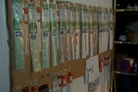
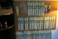
In closing a couple of images of my plastic stock mounted with push pins on corrugated cardboard.

A0MYFTk.jpg

xfbZKCN.jpg

Someday I'll find some cubicle wall dividers and do the set up properly. It saves a lot of time mounting your stock like this instead of rummaging through a couple hundred bags for the strip you need.

Next; Tools of the Trade...............
 
Last edited:

Blackadder

Well-Known Member
Gogsnik said:
A very professional looking build, carefully executed. I always have problems cutting plasticard strait but this whole build looks as neat as a pin.

I've been asked so often how I cut Plasticard and fabricate my models I've made a stock answer:

How are you getting such clean cut lines when you cut the plasticard?

Ah, that is the question I am asked most often and the answer cannot be repeated too many times because I think it the singular most important ability to achieve when anyone sets out to scratch build.

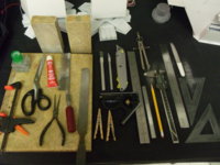
Regarding tools I don't use anything special. Aside from what you see here I do have a Dremel cordless, a cheap electric scroll saw, and a desk top belt sander all of which are rarely used.
url.jpg


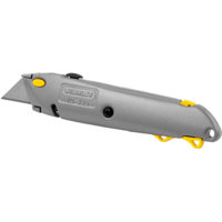
The main cutting tool I use is the retractable blade Stanley utility knife and I do have a see through plastic 12 inch scale to take measurements off of my LCD monitor.

I have two computer programs that allow me to scale the images and magnify them; ACDSee 14 and ULead Photo Impact 13 Editor.

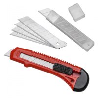
The biggest problem new scratchers have is using the wrong cutting tool. Craft cutting tools such as Xacto knives are useful and I have two pictured above, these are for fine detail work not for basic cutting and shaping.

As stated previously the Stanley Utility knife is the single most important tool in your inventory; it doesn't have to be of that manufacturer but of this type.
0007617410499_500X500.jpg
Small plastic handle snap off blade retractable knives of the type shown below are useless for hobby work, the blade
52875-01-1000.jpg

wobbles in the grip and you are more likely to injure yourself than to do any decent cutting with a tool of this type

In addition you will probably require:

A steel straight edge, sanding blocks (coarse and medium grit), and single cut 'farmers' file are used to get straight clean cuts and crisp 90° edges. You'll never get that with a 1/4 inch Xacto knife.

Another trick is score and snap; using the utility knife and straight edge score a line on the sheet plastic then a second to deepen the cut ( make additional passes for thicker sheets) then snap the sheet at the score line.

Always make two or more shallow cuts instead of trying to cut through with a single pass.

Dress your edges with the file and sanding blocks.


This should get you started, please ask for any clarification on the above.

As for detail, its hard to explain but my feeling is "More is better." A good supply of scrap styrene and bitz is essential and just try to duplicate what you see. Practice is the catch word here, there is no shortcut to experience and I am still learning myself.

Regarding the clothes pins I reverse the wood jaws in the spring for better clamping and I do have quite a few likewise with the modeling bar clamps. They are cheap here, I don't know if they are in New Guinea but you can order them on line from Amazon or Harbor Freight for about $2 bucks each:

I hope this helps but if not feel free to ask about anything that is unclear.
 

Blackadder

Well-Known Member
I imagine you have some power tools, or the arms and fingers of Hercules!!
As stated above I have a few basic power tools but I need them rarely, as for strength if you are using too much strength you are cutting wrong or using the wrong knife; the knife should do the work, you should merely guide it.


I would like to know you bonding agent in you didn't mind. I just used the stuff from Home Depot, and wondered if much had changed. ;)

I use Testors cement (Red Label not the Blue) for strength but it is slow drying. For quick bonding; Tamiya Extra Thin Cement. Hobby stores stock this type of cement
 

Blackadder

Well-Known Member
here you see I came back to this refreshed with new ideas and a firmer grasp on modeling techniques and not afraid to go 'where' a year ago I would have feared to tread..............I had put the landing gear on back burner for about a year while I worked on other projects rather than compromise with poor planning.

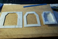
The new idea was to put the gear well in two sets of frames that gave me a bit of extra room for the retract cylinder and the oleo strut.

568HB4O.jpg

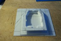
This also let me make this a modular subassembly so it could be removed and repair or upgraded if I so choose in the future.

5t0yd9m.jpg

Next; the mechanical portion of the Nose gear...........
 

zathros

*****SENIOR ADMINISTRATOR*****
Staff member
Administrator
Moderator
Have you ever tried using very thin cut off wheels to cut the Styrene. Since it removes the material, in cuts pretty well. I have had good success with it, and it is much quicker than a knife, and requires very little pressure. Just my two cents worth. :)
 

Blackadder

Well-Known Member
Searching "Cut off Wheels" I found discs for motor powered hand grinders.

http://www.homedepot.com/b/Tools-Hardware-Power-Tools-Grinders/N-5yc1vZc2fv

Styrene is much too easy to cut to employ such measures plus the clean up (both the piece and the workspace) is prohibitive since I work in my computer room/den. Try my score and snap method on a piece of scrap and see how it works for you; you can even score curves and circles using this method and there is virtually no waste and very little sanding to finish the cut edge.

Even the tiny Dremel Cutting disc is too much of a hassle to employ on sheet styrene in my experience, I even score and snap styrene tubing with relatively good results. but yes PVC would pose a challenge and for that I use an inexpensive electric Miter Saw; more on that later when I demonstrate forming the engine cowlings..........
 
Last edited:

Blackadder

Well-Known Member
The Retractable Nose Gear Cylinder Shock Strut Mechanism

Below is the system I came up with to allow the nose gear to retract and still compress when the weight of the model is on the extended foot plate.

This will allow the foot plate to extend forward to act as the nose gear bay door as in the original model but still be the landing foot pad when the gear is deployed.

The mechanism works but I still need to get the length right and I may need weaker springs. I'll have to see when the gear is installed in the model.

The components manufactured................
UHAqKgB.jpg

the components partially assembled................

zAshg9i.jpg

The shock strut in full extention.............
xUUvXWB.jpg

Compressing the shock strut allows 1.5 cm of travel...........

X5sPaE5.jpg

Just enough for my purposes.
 

Blackadder

Well-Known Member
Thanks for the reply,

The nose gear piston attach point is in place, now for the cylinder and trunnions............

05.jpg

Note the rectangular recess needed to allow for the retract cylinder trunnions.

Below is the nose landing gear removed from the gear well shown in the completely collapsed condition. The shock strut (oleo strut) is completely compressed so it will fit into the well. I am in the process of adding the gear well detail at the moment. Where does the time go.............

06.jpg

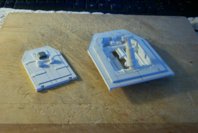
Here we see all the nose gear components including the foot pad and gear well reinforcement panels on the left. The lock pin forward of the foot pad, the gear well itself at the right rear. Forward of that is the shock strut and retract cylinder with their associate trunnion pins.
07.jpg

Here is the assembled nose gear showing the shock strut in collapsed position and the exterior of the well showing the axle sleeves for the trunnion pins that lock the gear trunions in place but allow them to swivel.

08.jpg

Front view of the nose gear assembled with the shock strut in full extension and the retract cylinder in full extension and foot pad attached.

09.jpg

Note the compactness of the mechanism, the whole of the structure less the foot pad is slightly more than 5/8 of an inch.

Next, the trial mounting in the aircraft.
 
Last edited:

zathros

*****SENIOR ADMINISTRATOR*****
Staff member
Administrator
Moderator
That's an impressive piece of engineering and construction.

This was really funny: "I've been asked so often how I cut Plasticard and fabricate my models I've made a stock answer:"

I was happy to the springs. Something this strong, you know people are going to want to push down to see if it works, and it also holds it up in place, and adds authenticity.

It's also amazing to see the plastic almost "welded" by the effect of the glue that really does bring these pieces together so well.

I get tempted to make some car models that are otherwise straight forward, except for areas of compound curves that paper quite can't do, not without water forming. )

You may wish to post this in the "Gallery" when done, and set one up for yourself. Anyone with a Facebook account can view it. Only models that have build threads can be posted there, and you can take some nice beauty shots to post up in there.. You can post a link back to the build thread, if your friends, or interested parties wish to see how to do it, and glean your words of wisdom. ;)
 

Blackadder

Well-Known Member
Thanks for the reply, for the time being I'll just stick with my threads but I'll check out the gallery.

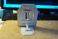
Nose Gear Installed Temporary

The nose gear mount plate is temporarily taped in place to see what the gear extension looks like. The foot plate is just attached with loose fitting plastic bushings.........

In the side view below the gear strut is canted forward but it can be set to vertical, I'm still ambivalent about that, I should have taken a image in the vertical position.

10.jpg

Dang! the bushing slipped out when I was setting the pose. There is too much gear well showing in the cargo bay. I'll have to shim up the exterior reinforcement plate.

11.jpg

A quarter view just because it looked good to me. Note the negative dihedral to the wings; the attach bolts are loose...............

12.jpg

Next, the detail...........
 

Blackadder

Well-Known Member
Barely had room for the light module bitz on the foot pad although everything else fitted with room to spare. still have so detailing to do on th top surface of the landing pad and the tread on the underside. but I am winding down for today and considered it time for an update.

13.jpg

Still can't make up my mind whether to cant the gear forward or make it vertical.

14.jpg

I decided to incline the nose gear angle for a more streamline profile and less extreme angle for the nose cargo ramp. The other reason for this is to put less pressure on the springs which will keep the gear from overly compressing.

15.jpg

With that I learned something about aircraft design today.

16.jpg

Now that I have established that area I can start on the retractable main gear.
 
Top