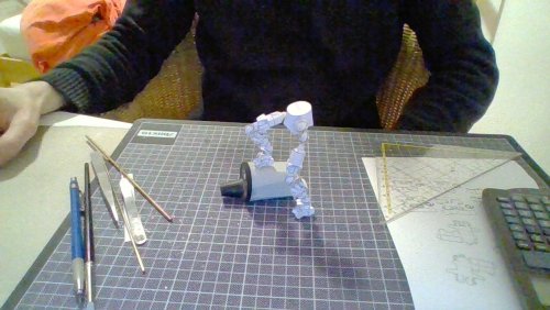
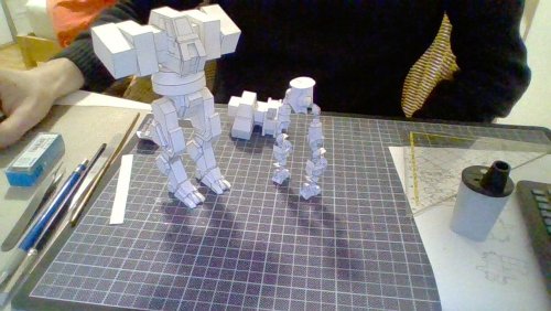
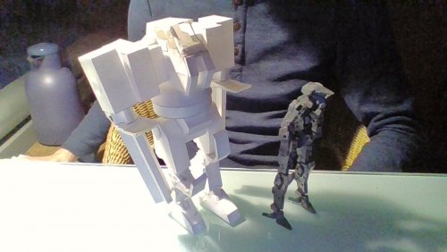
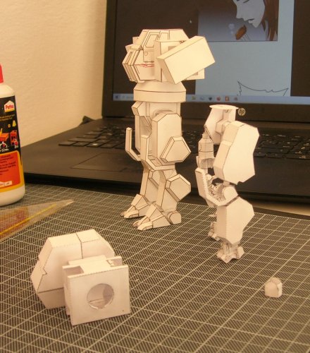
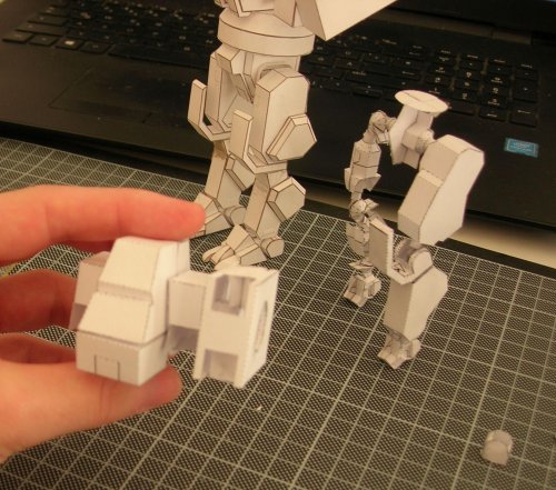
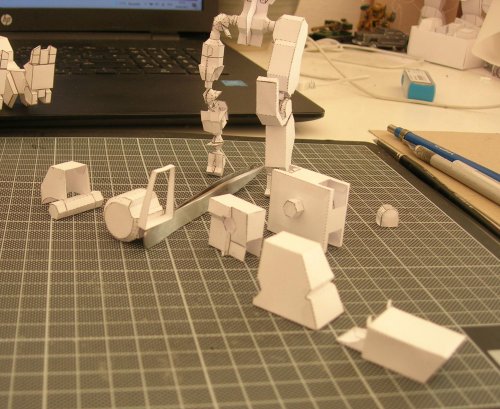
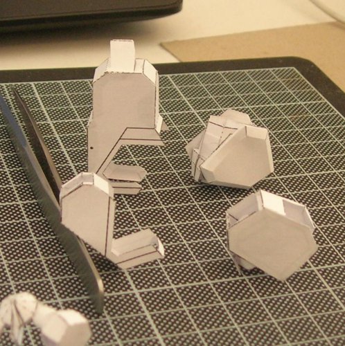
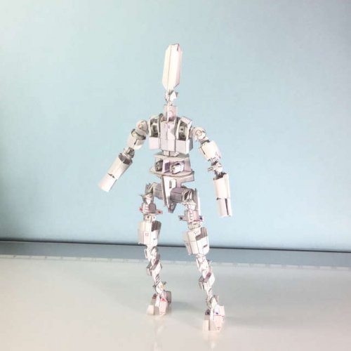
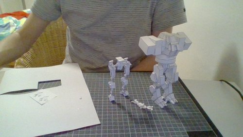
Kind of at a loss where to put these, but I suppose this is the best spot for what´s quasi an action figure. And sorry about the shitty photos, I have to find a charger for my old camera´s battery yet. Can´t just nab my old dad´s.
I felt like blog posting here like I´m trying to tell you all about some chili dish recipe, but I´ll cut to the point - I´m a bit obsessed with Battletech robots and after a lot of reflection, I settled on a number of criterions good papercrafts of them should fulfill to satisfy me. They are as follows:
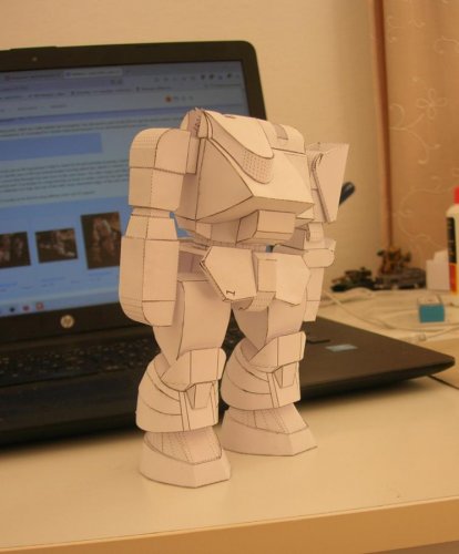
1) The lot should be in some existing scale and within the size range of all those already available giant robot plamos and there should be some relation to common AFV models. I eventually settled on 1/72.
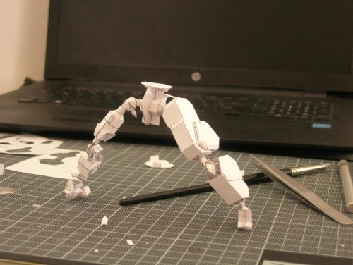
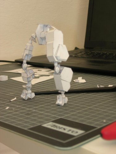
2) The lot should actually have a range of motion comparable to plamos. I wanna brag about my mechs, but that´s kinda hard when I´m building statues and everybody else has those fancy boy dolls
3) These machines, in their own fictional universe, have a ton of variants and paper is hella cheap, so making something that isn´t capable of representing at least the majority of those variants on a single chassin is a waste of my time. Heck, the game even has a specific class of machines that were deliberately built to hot-swap almost any system, meaning I´d have to wrest with the issue sooner or later anyway.
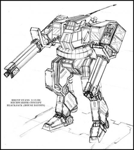
Point one - honestly - came down to a Sturmtieger´s upper casemate and missile launcher being an almost perfect proportional fit on the Blackjack variant design I used as a starting point. After scaling a buch of other mechs of other weight classes to it, I found that they all ended up within the size range between HG and MG kits, with the majority being around Frame Arms 1/100 models.
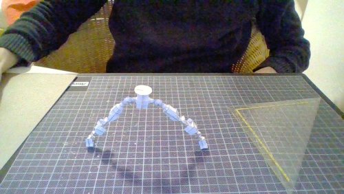
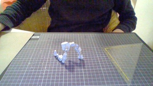
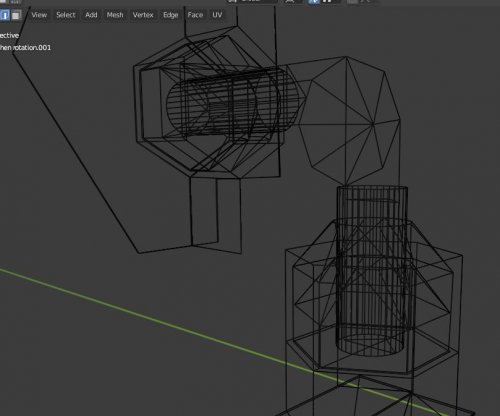
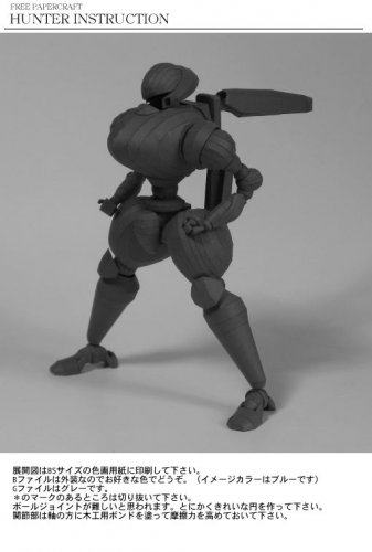
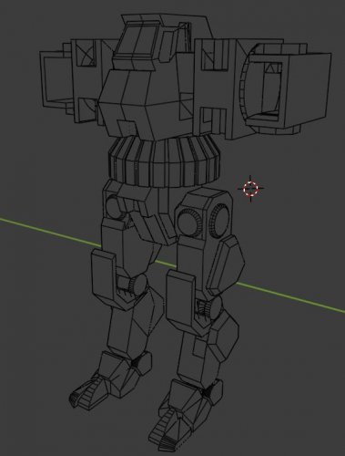
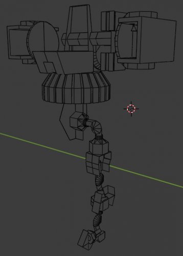
Point two stumped me for the longest time, as I, like many others, couldn´t really see beyond cylinders when it comes to creating articulation. It´s just that cylinders are pretty awful to make in paper and their tolerances are rather low if you´re aiming for decently stiff articulation, making using them a rather frustrating effort. Recently though, I found くじら 's v7.3 paper doll skeleton that had hinges based on cones and truncated cones and attained stability and stiffness through the interaction of stacked and glued paper. Now that one was nice. Much higher tolerances all around and parts that are actually designed to make use of paper and glue, plus his dedication to making the hinges and other parts that will come under stress easily replaceable was inspirational. The hip and arms are fixed in place and kept articulated with a little nub that grabs over an edge, the way 72 scale tank turrets are, but everything else is a variant of Kujira´s hinge system and skeleton architecture. Bless her/his/hir/zir/them/they/whatever prefered pronouns cheaseless efforts to make anime dolls.
Point three was... formally more problematic. BT art is famous for its lack of consistency in any port, barrel and other orifice that´s supposed to be pointed away from friendlies, but at least that naval mine launcher gave me some hint. Turns out that light naval autocannons fit on 72 scale mechs. Missile launcher tube diameters could be taken from standard ground-to-ground or multi-role RL missiles as well, even the largest twenty pack still fit into the arms of this 55 ton machine, which solved both the missile-problem and the highly non-standardized autocannon problem. The scifi-weapons, such as lasers, Gauss type weapons and PPCs I nabbed from illustrations and scaled to the 55 ton machine, with the caveate being that they should be smaller than autocannons and missiles as they´re generally lighter and more compact according to the game´s construction rules as well. Turns out I can put them on most designs up and down the weight scale, with minor issues only appearing in 20-ton machines. Fixing the guns into the body will be done with dovetail joints. I have some background in woodworking and triangles are easier to create in paper than pipes.
Should be enough material for an opening post. I´ll be back with better photos and more progress shots in the future.
I felt like blog posting here like I´m trying to tell you all about some chili dish recipe, but I´ll cut to the point - I´m a bit obsessed with Battletech robots and after a lot of reflection, I settled on a number of criterions good papercrafts of them should fulfill to satisfy me. They are as follows:
1) The lot should be in some existing scale and within the size range of all those already available giant robot plamos and there should be some relation to common AFV models. I eventually settled on 1/72.
2) The lot should actually have a range of motion comparable to plamos. I wanna brag about my mechs, but that´s kinda hard when I´m building statues and everybody else has those fancy boy dolls
3) These machines, in their own fictional universe, have a ton of variants and paper is hella cheap, so making something that isn´t capable of representing at least the majority of those variants on a single chassin is a waste of my time. Heck, the game even has a specific class of machines that were deliberately built to hot-swap almost any system, meaning I´d have to wrest with the issue sooner or later anyway.
Point one - honestly - came down to a Sturmtieger´s upper casemate and missile launcher being an almost perfect proportional fit on the Blackjack variant design I used as a starting point. After scaling a buch of other mechs of other weight classes to it, I found that they all ended up within the size range between HG and MG kits, with the majority being around Frame Arms 1/100 models.
Point two stumped me for the longest time, as I, like many others, couldn´t really see beyond cylinders when it comes to creating articulation. It´s just that cylinders are pretty awful to make in paper and their tolerances are rather low if you´re aiming for decently stiff articulation, making using them a rather frustrating effort. Recently though, I found くじら 's v7.3 paper doll skeleton that had hinges based on cones and truncated cones and attained stability and stiffness through the interaction of stacked and glued paper. Now that one was nice. Much higher tolerances all around and parts that are actually designed to make use of paper and glue, plus his dedication to making the hinges and other parts that will come under stress easily replaceable was inspirational. The hip and arms are fixed in place and kept articulated with a little nub that grabs over an edge, the way 72 scale tank turrets are, but everything else is a variant of Kujira´s hinge system and skeleton architecture. Bless her/his/hir/zir/them/they/whatever prefered pronouns cheaseless efforts to make anime dolls.
Point three was... formally more problematic. BT art is famous for its lack of consistency in any port, barrel and other orifice that´s supposed to be pointed away from friendlies, but at least that naval mine launcher gave me some hint. Turns out that light naval autocannons fit on 72 scale mechs. Missile launcher tube diameters could be taken from standard ground-to-ground or multi-role RL missiles as well, even the largest twenty pack still fit into the arms of this 55 ton machine, which solved both the missile-problem and the highly non-standardized autocannon problem. The scifi-weapons, such as lasers, Gauss type weapons and PPCs I nabbed from illustrations and scaled to the 55 ton machine, with the caveate being that they should be smaller than autocannons and missiles as they´re generally lighter and more compact according to the game´s construction rules as well. Turns out I can put them on most designs up and down the weight scale, with minor issues only appearing in 20-ton machines. Fixing the guns into the body will be done with dovetail joints. I have some background in woodworking and triangles are easier to create in paper than pipes.
Should be enough material for an opening post. I´ll be back with better photos and more progress shots in the future.


")