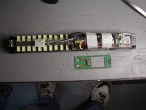
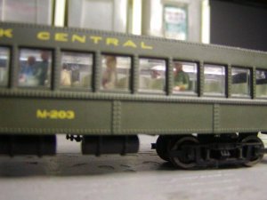
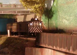
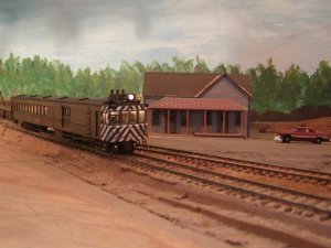
I had commented on another thread recently that I had refained interest in the hobby, and that there were a couple projects I would get to next. Well, this wasn't one of them! Just goes to show why things take so long! As I was repairing a pair of LL GP7's I came across an NCE decoder I bought long ago. I remebered I had bought it to use in the doodlebug, which I bought when it was first released, has it been 6 years or so? I had removed the shell and found that the 8 pin DCC socket was mounted on a pcb, facing up and immediately beneath the roof, so that standard DCC plugs on decoders did not have clearance. I know back then there was a flatter plug available, and suppose there still is, but I had never ordered it, and decided yesterday to just pull the pcb out and hardwire the decoder. There is really not much to the installation, certainly doesn't seem to warrent a thread, but I'm posting it anyway, perhaps newbies will benefit, and also you guys will know I am doing something!
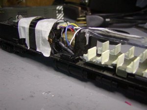
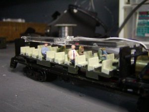
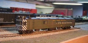
After removing the pcb, I measured the thickness of the decoder and found it was just a bit less than the pcb with socket. So I was good there. I taped it in place and there is only one place where the solder connections can sit, between the motor and passenger compartment, above and alongside the flywheel. So the leads from the decoder had to be cut real short. This made connecting the wires a bit finicky, at least to my clumsy fingers. But doable, no doubt. You'll see in the photos how I laid these joints into the available space. The headlight was another question, it was mounted on the pcb I had removed, and the pcb had a hole which sat on a boss in the molded weight, to keep it in the right position for the light bar. I decided to saw off the end of the pcb, and solder wires to the pads on the underside. This way it is stil positioned correctly. You can see the small bit of the pcb with headlight in the photo, the rest of the pcb is on the workbench to show how it was on the stock model. There is another light, in the passenger compartment. I decided to wire both together and did so to both the yellow and white leads, so they are not dependant on direction. I can turn them on when I run the unit, and off while it is sitting on the powered layout, to extend the bulb life. As I said, not much to it!
After removing the pcb, I measured the thickness of the decoder and found it was just a bit less than the pcb with socket. So I was good there. I taped it in place and there is only one place where the solder connections can sit, between the motor and passenger compartment, above and alongside the flywheel. So the leads from the decoder had to be cut real short. This made connecting the wires a bit finicky, at least to my clumsy fingers. But doable, no doubt. You'll see in the photos how I laid these joints into the available space. The headlight was another question, it was mounted on the pcb I had removed, and the pcb had a hole which sat on a boss in the molded weight, to keep it in the right position for the light bar. I decided to saw off the end of the pcb, and solder wires to the pads on the underside. This way it is stil positioned correctly. You can see the small bit of the pcb with headlight in the photo, the rest of the pcb is on the workbench to show how it was on the stock model. There is another light, in the passenger compartment. I decided to wire both together and did so to both the yellow and white leads, so they are not dependant on direction. I can turn them on when I run the unit, and off while it is sitting on the powered layout, to extend the bulb life. As I said, not much to it!