- Apr 5, 2013
- 13,876
- 10,216
- 228
You guys are really banging away at this, excellent!!")
") That head is going to be the death of us, but we WILL figure it out eventually through use of duct tape, bailing wire, chewing gum and a LOT of divine guidance! Gandolf is on an interesting path and has done a lot of hard work, which is to be commended.
That head is going to be the death of us, but we WILL figure it out eventually through use of duct tape, bailing wire, chewing gum and a LOT of divine guidance! Gandolf is on an interesting path and has done a lot of hard work, which is to be commended.Just for the record, I have been working on the Minbari Sharlin from the same site. The models have 2 or 3 of the same models super imposed on each model. If you don't delete the copied models in the same space, you have all kinds of problems, and a file that is three times bigger than it should be. I do not know why they did this. I discovered this when I selected the top section of the Minbari ship, and the selection had two drop down alternatives. I deleted one section, no change, I deleted the next same section, no change, I deleted the final section, and it was going, I went back one step to retrieve it, then proceeded deleting all of the superfluous models within models till I got to only one copy. This causes much errors, and can be a great impediment if you don't get rid of these. This is really bad CAD practice (Great CAD model though) and I think it is done purposely, especially if you explode the sections, then try to reconstruct them.
I have now converted the Sharlin to a fully Nurbs model, and can work with it line by line, inserting control points if necessary. Just in case you didn't know.
 Big ship!! Will definitely want to see pics of that when you start building it. I wonder why they superimposed 3 models on the same model? That's kind of redundant isn't it? Wastes memory too.


Oh...ok you are doing a different version...


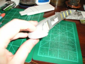
Test build main wing.
Here's the main wing (i.e. pita pocket):
One of the wings have tabs and the other side does not. Also, tried to experiment with forming the engines from the existing cardstock around the engine areas (see below). I don't think that it worked too well and recommend that separate engine constructions be made by inserting from the front to the back. This would give a more round shape to the back.
In constructing the wing, you start by gluing the center tab of the tabbed wing to the non tab wing
View attachment 155308
Next, you glue the tabs from one side of the wing working form the center to the outer most portion of the wing.
View attachment 155309
Reate what you did above to the other side. Back side of the wing. Note the tabs at the back.
View attachment 155310
Top view. Both sides joined together. Recommend making dashed line marks at the front for placement of the front struts, engine nacelles (on either side of the top vertical stabilizer), as well as lines for the top and bottom vertical stabilizers.
View attachment 155311
Inside view joined together. Note the inside tabs.
View attachment 155312
1st left engine joined.
View attachment 155313
Engines have been colored in with a highlighter. The side portions form triangular pieces instead of rounded more oval shaped sides on either sides of the engines.
View attachment 155314
That's it for now.
Sky Seeker
:tank:
Now the man tells me!I just was re-viewing..and for future reference...on the wings..each BLACK line radiating to the center ..is a cut line! You have to take a thin section out and tab them back together...the dashed line around the edge is a fold line..you then roll the edge down to form the back curve...they are all EXTREMELY SUBTLE! and tricky! but it makes for a solid and nicely curved wing...!


 :Computer::nailbiting::facepalm: - correctable though). Minor curve near the tip on one side that caused a huge deflection when assembling the turret plates to the main wing. Fixed though. Have to be careful in future constructions for the unwary.
I did a new design head object for your build , from the ground up......at least it should be something you can adapt.. just can't get it to you as yet till the server error is fixed...sorry can't show a picture either...???
:frak: but it is ready..dropped it into Pepakura as it was a very simple mesh, very clean... and you should be able to scale to what-ever size you need and so-forth..as well as drop to bmp and texture.. formed it from the 3views of the original Centauri-Vorchan by Lc4Hunter...the same as your 3views..but I did not make it quite as pronounced in the curves..as that would have lead to many more problems..or back to the same-o-same-o...get it to you ??? asap!!

Gonna see if it works or not....
View attachment 156444
Hoora!!! There ya go Seeker your new Vorchan Head object..now to see if I can get it to ya!!
Could you get the smaller unfolded portion above (on the left of the pic above) portion to me as well? I will compare and contrast, then build. See you got into the box bit. LC4Hunter did some good work. Now to scale it up or down a little to make it fit with what we have so far!