Magnetometer (MAG) boom arm:
I've saved this till last ... you'll see why below!
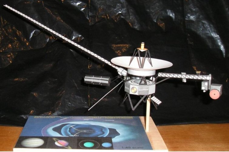
There are 2 low-field magnetometers on the Voyager spacecraft. One is midway down the 13m (43 feet) arm and the other is at the far end. How did they get a 13m long boom stored and then deploy it on a compact payload in the 1970s? Another amazing feat of engineering. The arm is called an Astromast. "The Astromast is a fiberglass boom made of three longitudinal rods that run the length of the boom — thirteen meters, in Voyager's case. The rods are held in a triangular cross-section by fiberglass trusses and diagonal filament struts, all fastened with flexible joints. The entire boom is collapsed by twisting it and laying it in coils into a small canister — Voyager's was only about 70 centimetres in length. Deployment takes place in a controlled fashion by slowly letting out a central lanyard as the boom extends under the spring-force of its twisted fiberglass rods. The boom, and the instruments mounted to it, rotates as the boom deploys." https://www.quora.com/How-did-Voyagers-1-and-2-unfurl-so-to-speak-from-the-space-capsule This method of placing instruments away from spacecraft has been used on a number of other craft too, before Voyager and since.
The article quotes the above from a book, Deep Space Craft by Dave Doody (a NASA Engineer, amongst other things he worked on the Voyager programme). The page explaining the Astromast technology, including a photograph of the mast stored before deployment on Galileo, is available thanks to Google Books on p176 here https://books.google.co.uk/books?re...VUC&q=astromast#v=snippet&q=astromast&f=false There's a lot wrong with the internet and how it's used in the world today, but it's also an incredible knowledge-base and rich resource for those researching facts like these.
Here's a video of the later Europa Clipper magnetometer boom deployment to see how it works in practice
MAG Boom Greebling - making a "skeletal" hollow structure like the instrument truss
Here's a photo of the finished model from the instructions pdf showing the MAG boom - as it's quite narrow I can see why it's been done this way, folding a 25cm triangle with sides of less than 4mm is hard enough ...

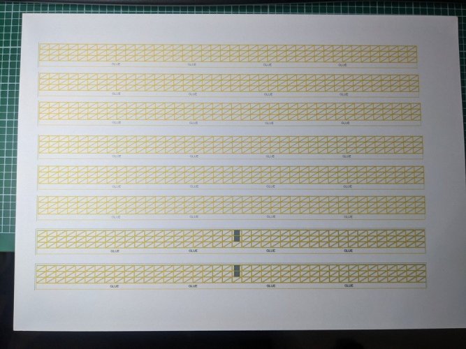
But then I did manage to do something with the instrument arm didn't I ... ok, I'll have a go at doing the same! I took the image and converted it from black to yellow in GIMP and printed a page on 300gsm card (for strength and stability at such a length) with a few copies of it.

I'll have a go and see if it's achievable. Wish me luck!
I've saved this till last ... you'll see why below!
There are 2 low-field magnetometers on the Voyager spacecraft. One is midway down the 13m (43 feet) arm and the other is at the far end. How did they get a 13m long boom stored and then deploy it on a compact payload in the 1970s? Another amazing feat of engineering. The arm is called an Astromast. "The Astromast is a fiberglass boom made of three longitudinal rods that run the length of the boom — thirteen meters, in Voyager's case. The rods are held in a triangular cross-section by fiberglass trusses and diagonal filament struts, all fastened with flexible joints. The entire boom is collapsed by twisting it and laying it in coils into a small canister — Voyager's was only about 70 centimetres in length. Deployment takes place in a controlled fashion by slowly letting out a central lanyard as the boom extends under the spring-force of its twisted fiberglass rods. The boom, and the instruments mounted to it, rotates as the boom deploys." https://www.quora.com/How-did-Voyagers-1-and-2-unfurl-so-to-speak-from-the-space-capsule This method of placing instruments away from spacecraft has been used on a number of other craft too, before Voyager and since.
The article quotes the above from a book, Deep Space Craft by Dave Doody (a NASA Engineer, amongst other things he worked on the Voyager programme). The page explaining the Astromast technology, including a photograph of the mast stored before deployment on Galileo, is available thanks to Google Books on p176 here https://books.google.co.uk/books?re...VUC&q=astromast#v=snippet&q=astromast&f=false There's a lot wrong with the internet and how it's used in the world today, but it's also an incredible knowledge-base and rich resource for those researching facts like these.
Here's a video of the later Europa Clipper magnetometer boom deployment to see how it works in practice
MAG Boom Greebling - making a "skeletal" hollow structure like the instrument truss
Here's a photo of the finished model from the instructions pdf showing the MAG boom - as it's quite narrow I can see why it's been done this way, folding a 25cm triangle with sides of less than 4mm is hard enough ...

But then I did manage to do something with the instrument arm didn't I ... ok, I'll have a go at doing the same! I took the image and converted it from black to yellow in GIMP and printed a page on 300gsm card (for strength and stability at such a length) with a few copies of it.

I'll have a go and see if it's achievable. Wish me luck!


