Y-WING BUILD - Construction continues...
- Thread starter Chuffy70
- Start date
You are using an out of date browser. It may not display this or other websites correctly.
You should upgrade or use an alternative browser.
You should upgrade or use an alternative browser.
Cool, where do I send the cash..?After advanced builder you can become
master paper modeler or master paper designer.

- Apr 5, 2013
- 13,498
- 9,549
- 228
People just get better. When you reach a point where people can't tell what it's made of, or if properly photographed, that it's a model, then I believe, IMHO, you've reached the top echelon of builders. 
- Apr 5, 2013
- 13,498
- 9,549
- 228
Right, next on the agenda is the rear fins or vanes.
There's a fair bit going on here, so I'll take it in stages.
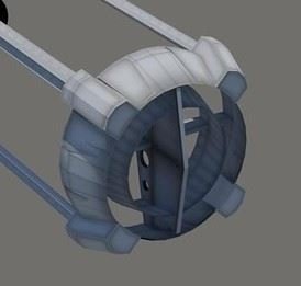
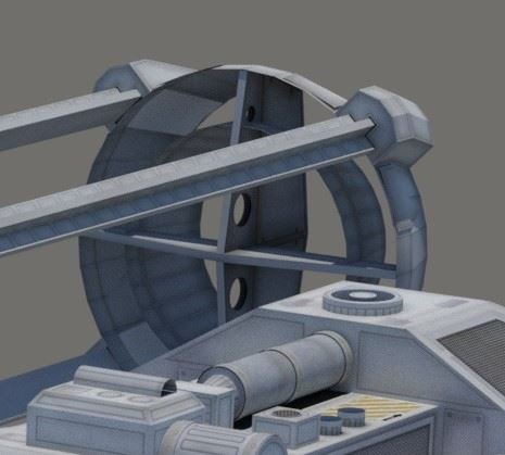
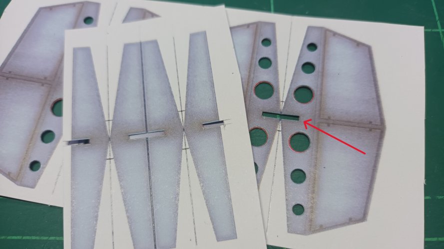
ENGINE PAGE 5 consisting parts for the inner cross segment.
All red areas are to be removed, the circles could be marked over in black, but the rectangles will need to be cut out.
I choose not to use all the parts here - the central upright with the holes I only used enough for four laminations and the horizontal section was built up to match the slot.
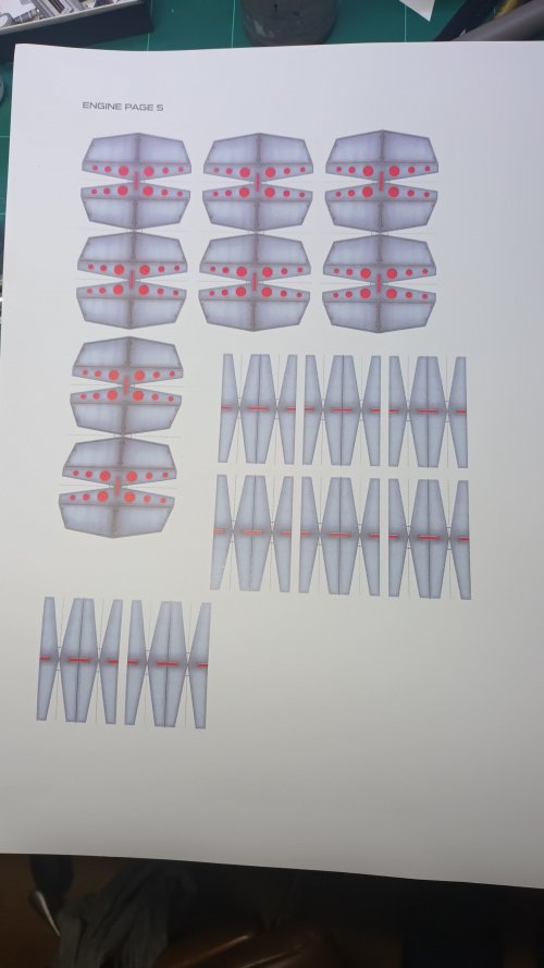
All slots opened up & holes punched, of which some were better than others, so I just picked the best of the bunch. I prefer to punch my holes before cutting the piece out, as there's less chance of ruining the part.
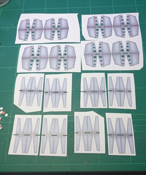
To get a good fit, the horizontal needs to be built up to fit your slot.
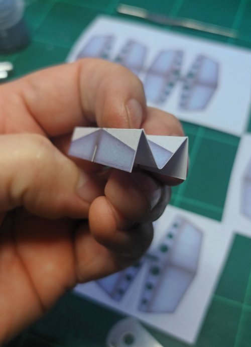
The horizontal was creased along all visible lines into an 'M' shape and spare singles used to thicken the part to fit the slot.
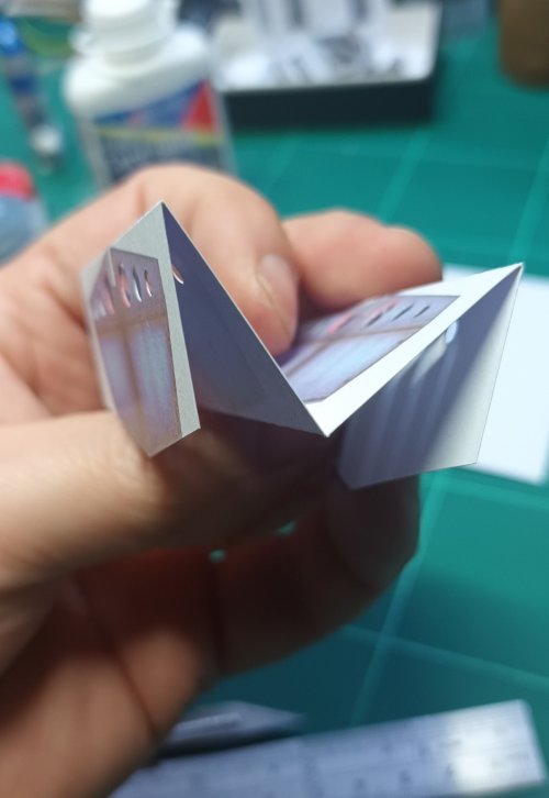
The vertical plane was also folded as an 'M' - which I felt the four laminations was sufficient. I did all of the pairs of parts, and picked out the neatest ones for the build.
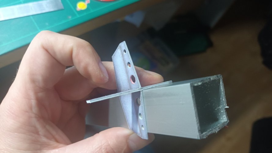
Using a piece of aluminium box section I had to hand was ideal to keep the part at right angles. Where the parts met, I followed up the join afterwards with cyanoacrylate/superglue to strengthen the joint...
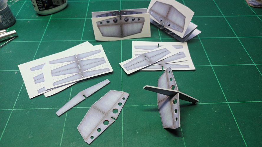
Spare and assembled parts.
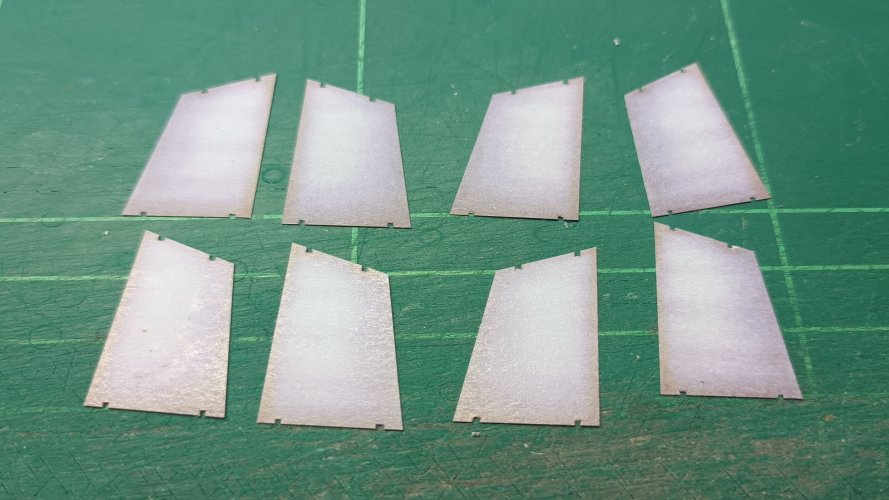
To add further detail here, I cut away the panels on the spare parts...
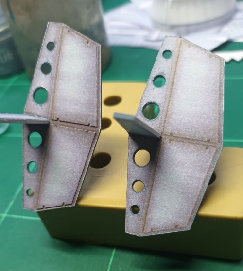
…and added them to the uprights for better definition - Left added, right as printed.
ALL FOR NOW, UP NEXT THE INNER CIRCLE
THANKS FOR WATCHING...
There's a fair bit going on here, so I'll take it in stages.


ENGINE PAGE 5 consisting parts for the inner cross segment.
All red areas are to be removed, the circles could be marked over in black, but the rectangles will need to be cut out.
I choose not to use all the parts here - the central upright with the holes I only used enough for four laminations and the horizontal section was built up to match the slot.

All slots opened up & holes punched, of which some were better than others, so I just picked the best of the bunch. I prefer to punch my holes before cutting the piece out, as there's less chance of ruining the part.

To get a good fit, the horizontal needs to be built up to fit your slot.

The horizontal was creased along all visible lines into an 'M' shape and spare singles used to thicken the part to fit the slot.

The vertical plane was also folded as an 'M' - which I felt the four laminations was sufficient. I did all of the pairs of parts, and picked out the neatest ones for the build.

Using a piece of aluminium box section I had to hand was ideal to keep the part at right angles. Where the parts met, I followed up the join afterwards with cyanoacrylate/superglue to strengthen the joint...

Spare and assembled parts.

To add further detail here, I cut away the panels on the spare parts...

…and added them to the uprights for better definition - Left added, right as printed.

ALL FOR NOW, UP NEXT THE INNER CIRCLE
THANKS FOR WATCHING...
Last edited:
Great idea to add the extra panels it make this part so much better.
A little goes a long way...Great idea to add the extra panels it make this part so much better.
Thank youThat looks very good!
With the internal crossmember section done it's time to move onto the internal and outer ring.
These parts are stated as ENGINE PAGE 6 & ENGINE PAGE 7
Page 6 contradicts itself by asking to be printed grey on the reverse... But page 7 is the reverse.
Well that's how I take it, so I'll progress with sandwiching the parts together.
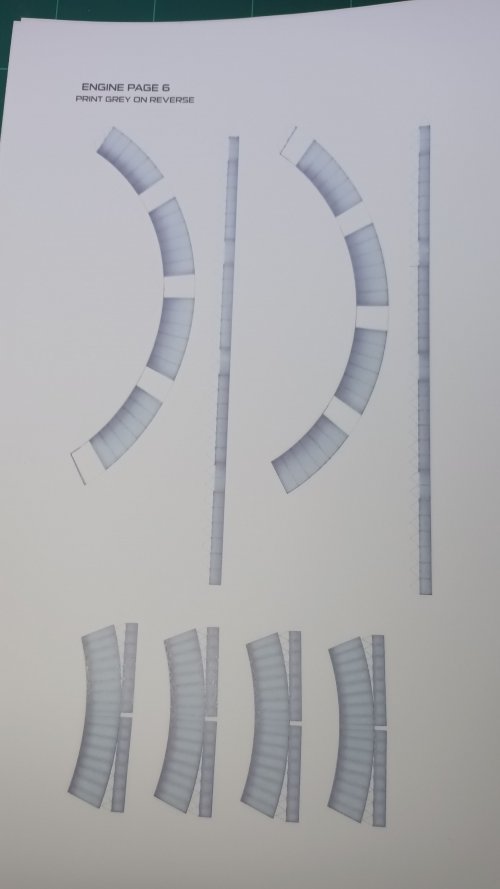
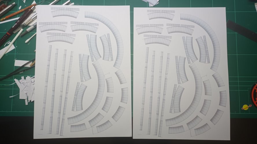
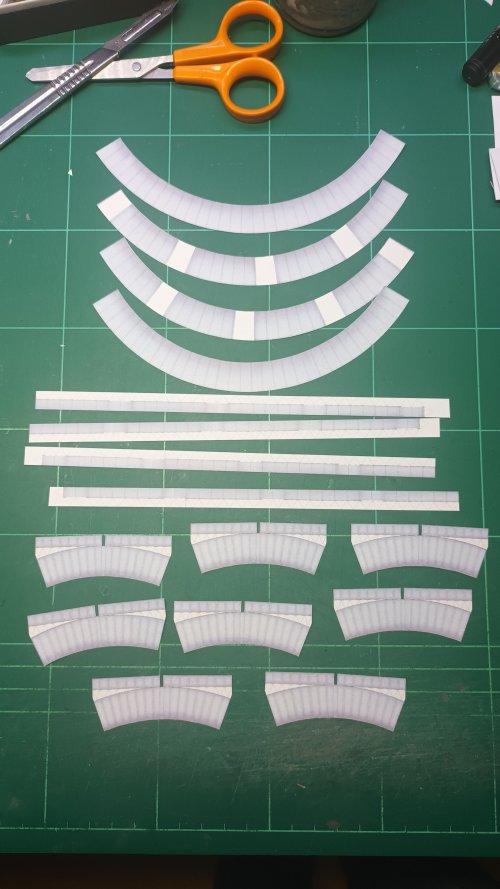
A slight uncertainty was crossing my mind for some reason on what appears to be a simple construction. With that I cut the properly printed parts out and copied x2 on my basic copier at home so that I could test-fit these parts before progressing onto the better prints.
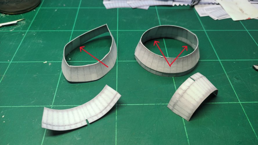
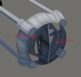
Rough and ready construction showed me (double arrows) if I kept one side open I could leave tabs on the smaller outer rim, which would enable me to insert, rather than butt join. I was of the opinion here that this will help obtain a good circle.
The single arrow shows a white rectangle in the inside - This I believe to be incorrect, as this would be the placement guide for the strut receivers to be attached to 'on the outside'
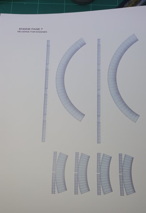
The supplied image with the parts also showing the supposed 'wrong orientation' of the placement guides.
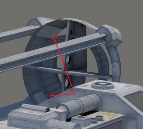
I had obtained enough information from the rough build to carry on with the proper parts. I will start with the internal rings which attach to the inner cross members as arrowed.
Before constructing them, I added crease lines, just to add a bit of dimensionality to them.
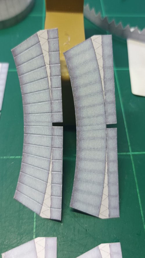
The tabs were kept, but I shortened them and cut the tops off to disguise their shape should they become visible through the paper during the sandwiching process.
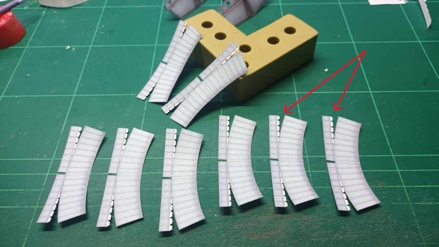
All parts formed.
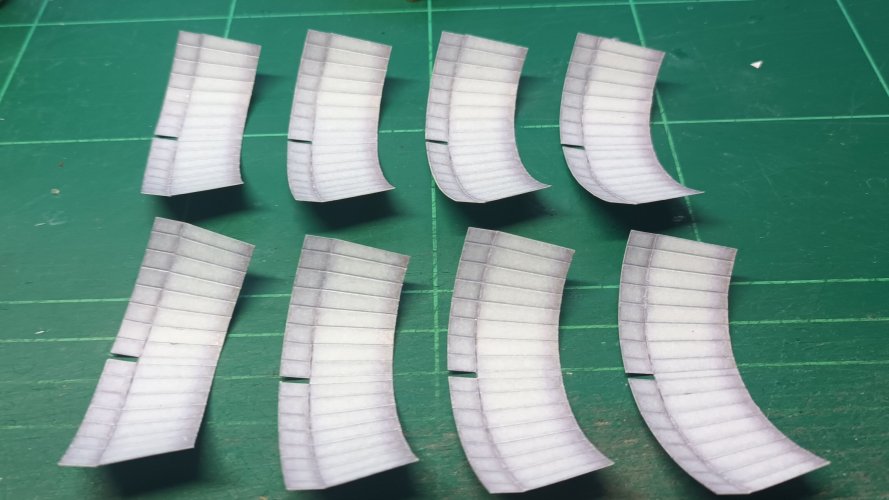
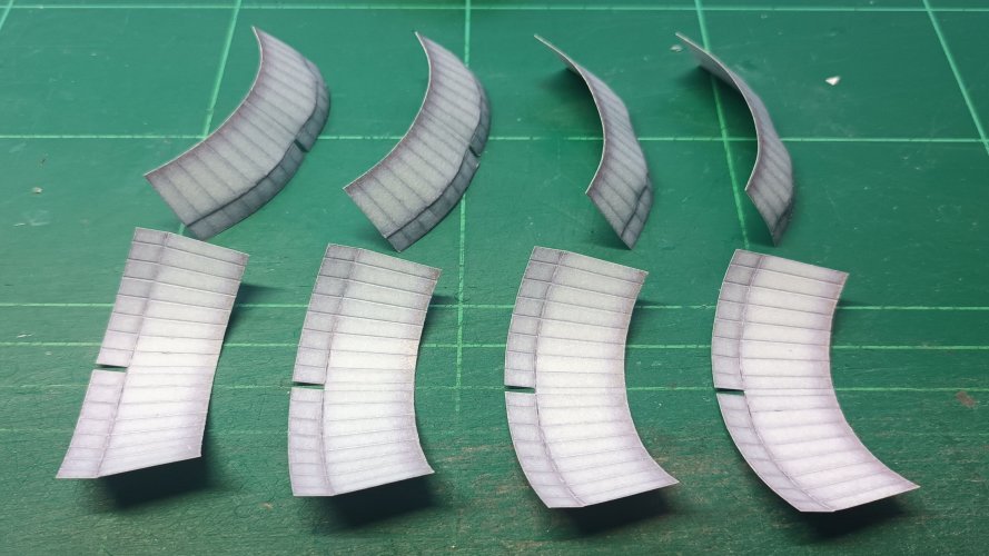
Centre point was chosen and glued outwards.
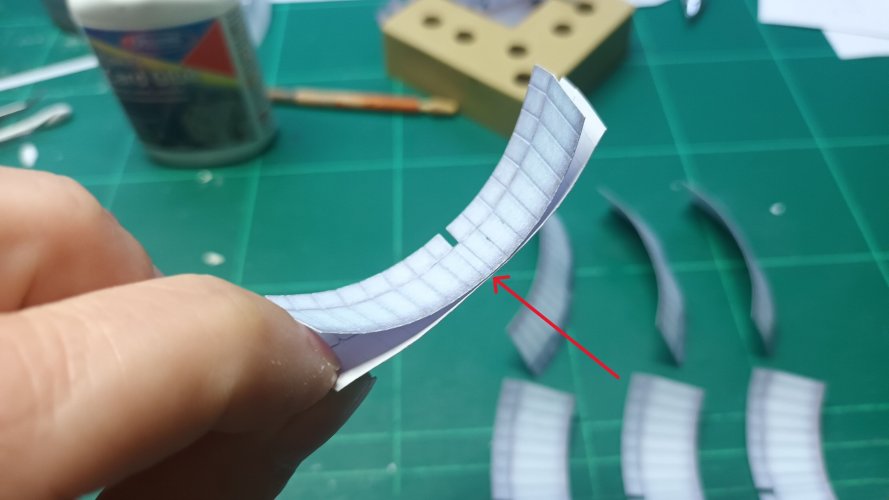
There's no fixing location, so looking at the reference photos I went for the middle between the two circles, marking the outer to help align the other-side.
The blue arrow is pointing to where the slot goes over the crossmember, this is not glued at the moment, which will enable me to move it in and out hopefully helping obtain a decent shape.
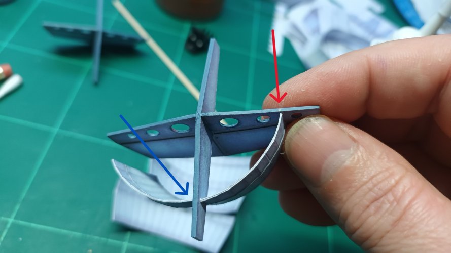
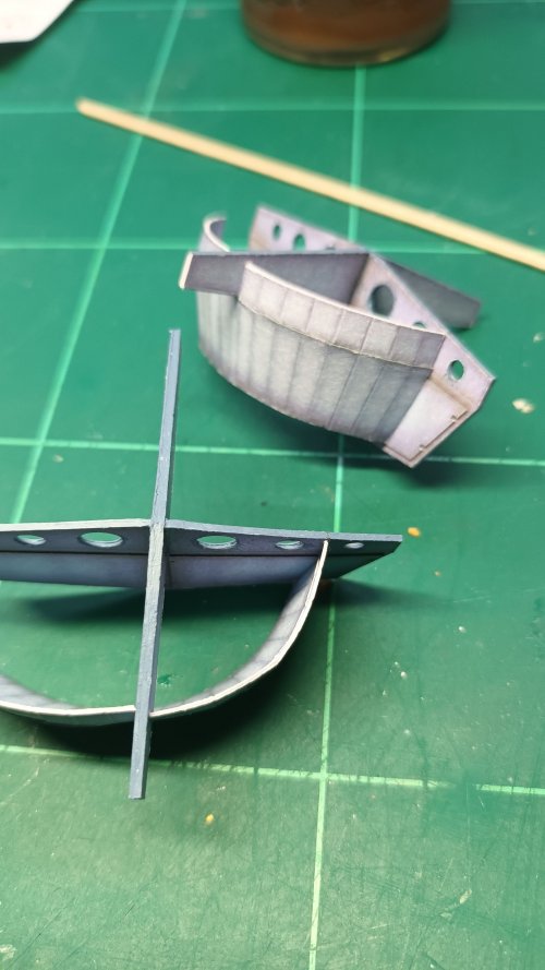
Partly finished for now and not looking particularly brilliant, buy hey-ho at least I have two small models of the 'Odyssey' from Ulysses 31'
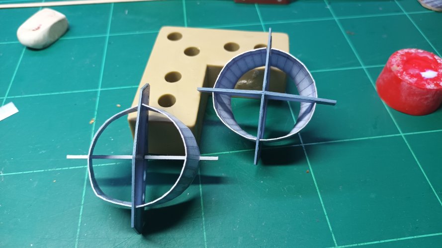
THANKS FOR WATCHING, AND WE'LL UPDATE TOWARDS THE END OF THE WEEK WITH MORE HOT RING ACTION...
These parts are stated as ENGINE PAGE 6 & ENGINE PAGE 7
Page 6 contradicts itself by asking to be printed grey on the reverse... But page 7 is the reverse.
Well that's how I take it, so I'll progress with sandwiching the parts together.


A slight uncertainty was crossing my mind for some reason on what appears to be a simple construction. With that I cut the properly printed parts out and copied x2 on my basic copier at home so that I could test-fit these parts before progressing onto the better prints.


Rough and ready construction showed me (double arrows) if I kept one side open I could leave tabs on the smaller outer rim, which would enable me to insert, rather than butt join. I was of the opinion here that this will help obtain a good circle.
The single arrow shows a white rectangle in the inside - This I believe to be incorrect, as this would be the placement guide for the strut receivers to be attached to 'on the outside'

The supplied image with the parts also showing the supposed 'wrong orientation' of the placement guides.

I had obtained enough information from the rough build to carry on with the proper parts. I will start with the internal rings which attach to the inner cross members as arrowed.

Before constructing them, I added crease lines, just to add a bit of dimensionality to them.

The tabs were kept, but I shortened them and cut the tops off to disguise their shape should they become visible through the paper during the sandwiching process.

All parts formed.


Centre point was chosen and glued outwards.

There's no fixing location, so looking at the reference photos I went for the middle between the two circles, marking the outer to help align the other-side.
The blue arrow is pointing to where the slot goes over the crossmember, this is not glued at the moment, which will enable me to move it in and out hopefully helping obtain a decent shape.


Partly finished for now and not looking particularly brilliant, buy hey-ho at least I have two small models of the 'Odyssey' from Ulysses 31'

THANKS FOR WATCHING, AND WE'LL UPDATE TOWARDS THE END OF THE WEEK WITH MORE HOT RING ACTION...
Middle part of the rear vane section completed its time for the outer ring.
Each ring was sandwiched as per the inner parts
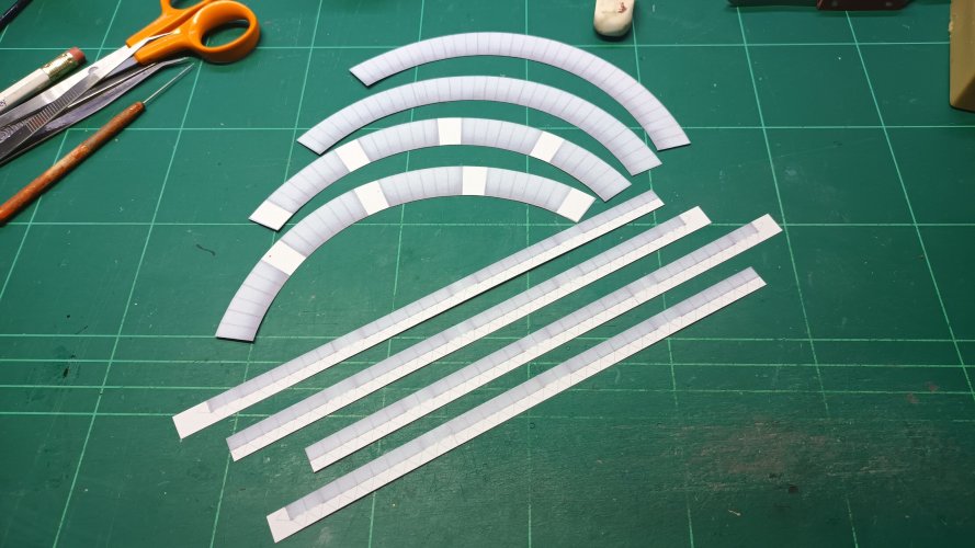
Added tabs to the internal surface
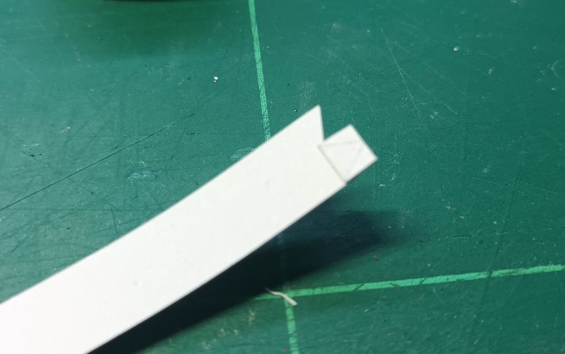
With the parts glued in the middle, one end was left open, so that I could insert B into A
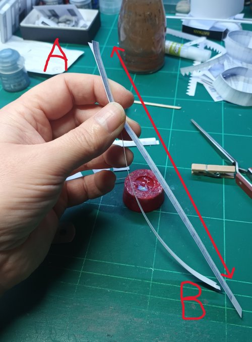
Before inserting the tab, I glued the final part of the two pieces together and tightly held them allowing the triple sandwich of both parts and the inner tab to crush down into each other, making for a less visible join
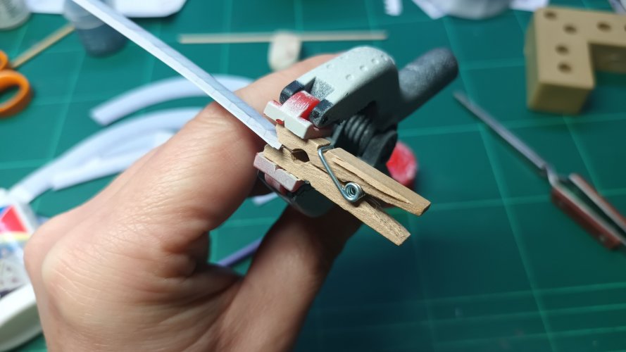
I cut off the triangular tips of the tabs on the smaller of the two outer rings, before assembling.
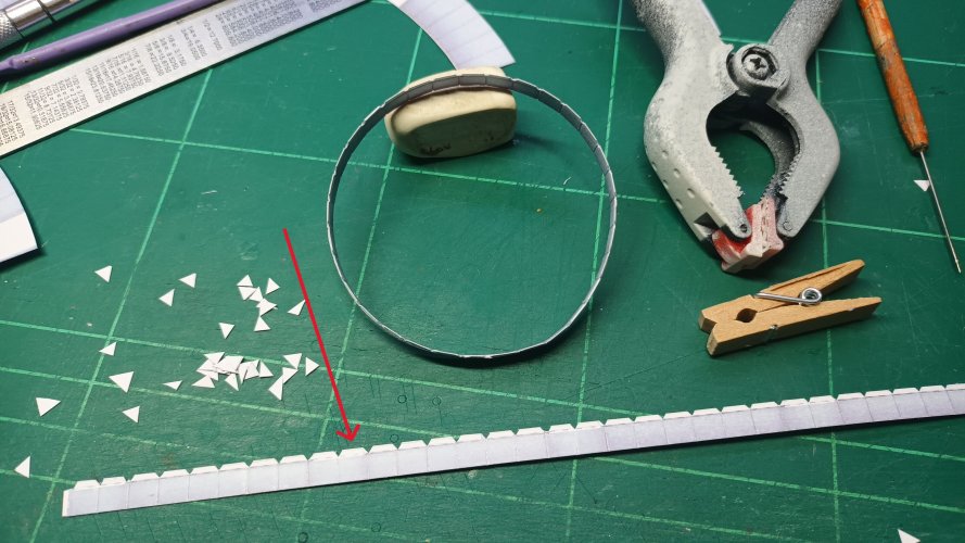
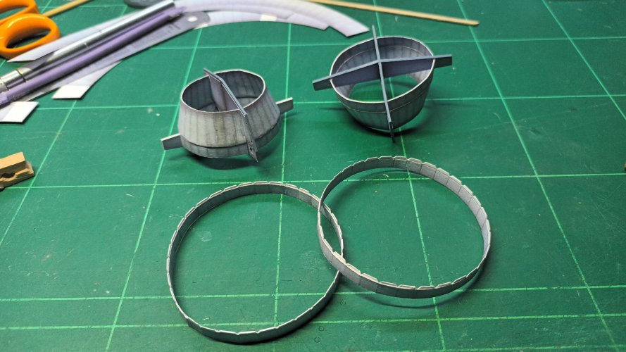
Somewhere I missed taking photos of the the curved outer ring, but assembly was just sticking two bits together.
However, my idea was to leave the edge were the thinner strip attaches un-glued so that I could insert the thinner ring into it, rather than butt-joining.
Sadly I glued down the wrong edge and I had to open up the piece to accept the part. I could have reprinted the piece, but I wanted to carry on and see if I could salvage anything.
Blue arrows was the edge I'd left open...
Green line was where I was only supposed to glue...
Red arrows was where I had to re-open the part..!
"doh!"
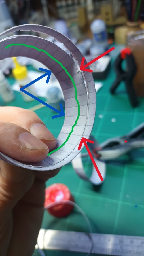
After a struggle and a few swear words the two parts were married, although some areas were badly damaged in the separation.
However, I did have some parts leftover from the pre-test assemblies, although the quality was less resolution than the proper parts, I thought some kind of repair job could take place.
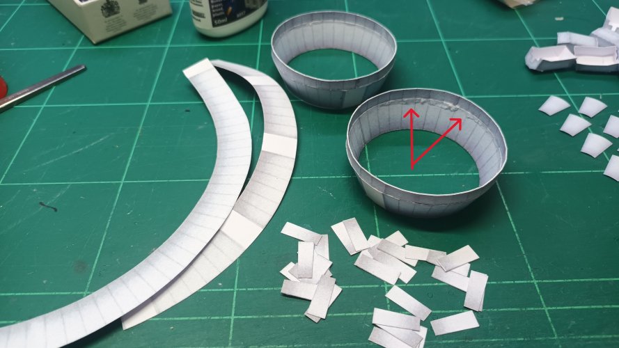
As the Y-Wing is inherently a beaten up starfighter, the cut outs from the spare parts were added to disguise the damage, leading to an 'added' visual interest to the area. Most of this is hidden anyway, so I wasn't really fussed as to how it looked any way... but patch field repairs if you will...
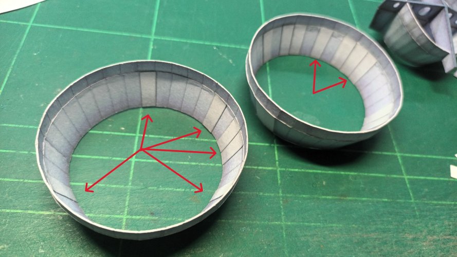
Taking care to note the orientation of the crossmember sections, they were then added into the outer rings, also noting the white placement panels on the outside, rather than inside as pointed out in the previous post.
Fit was good here and the dodgy inner-circles don't look as bad as they did.
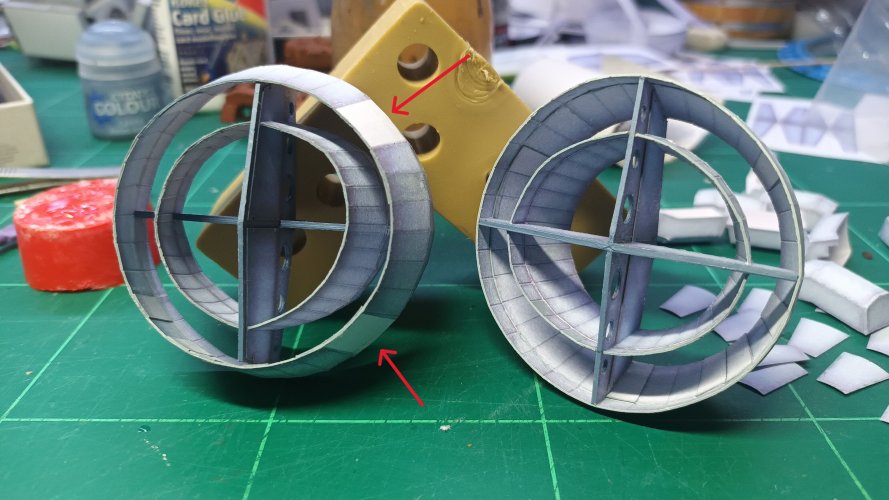
The rings will have more details added to them later. The two-part pieces are only decorative elements and the multi-fold pieces are slots for the 'T' struts to fit in. I will not attach these pieces until I have made the T struts, in case there are any problems with the fit.
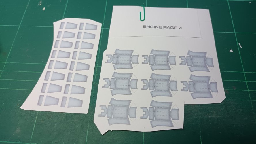
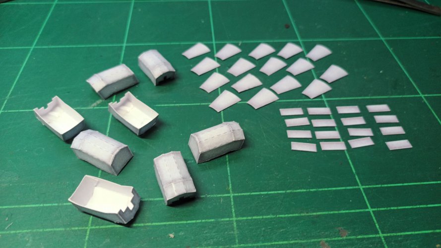
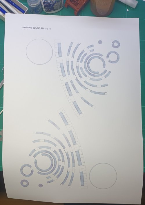
From one end of the engine to the other - Cone assembly is next and probably the most looked at part, aside from the canopy on the model.
Parts are from ENGINE CASE PAGE 4.
Rings assembled and I added a number sequence inside to help the build, as some look exactly the same.
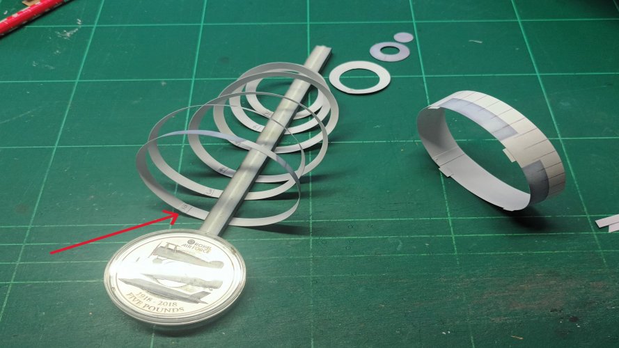
As the assembly tapers inward to form a cone, the first set of added tabs were feathered into tiny strips, my thinking being they will bend easier than a solid tab.
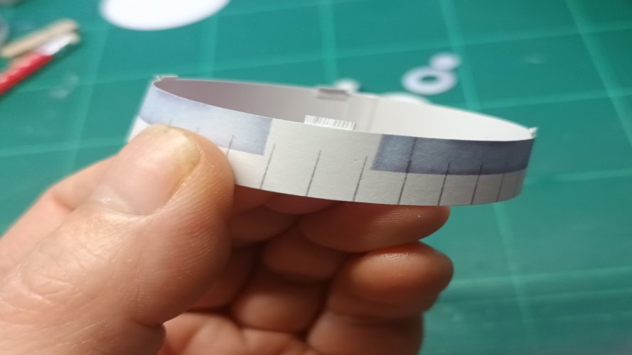
Further tiny tabs were fitted to the other sections which allowed for greater flex, rather than the aforementioned larger solid tabs.
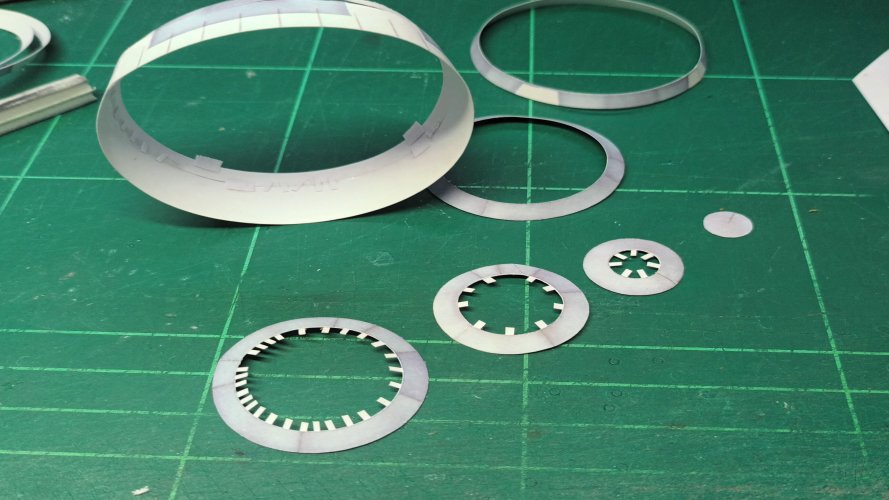
That's all for today. Thank you for watching, as always.
Each ring was sandwiched as per the inner parts

Added tabs to the internal surface

With the parts glued in the middle, one end was left open, so that I could insert B into A

Before inserting the tab, I glued the final part of the two pieces together and tightly held them allowing the triple sandwich of both parts and the inner tab to crush down into each other, making for a less visible join

I cut off the triangular tips of the tabs on the smaller of the two outer rings, before assembling.


Somewhere I missed taking photos of the the curved outer ring, but assembly was just sticking two bits together.
However, my idea was to leave the edge were the thinner strip attaches un-glued so that I could insert the thinner ring into it, rather than butt-joining.
Sadly I glued down the wrong edge and I had to open up the piece to accept the part. I could have reprinted the piece, but I wanted to carry on and see if I could salvage anything.
Blue arrows was the edge I'd left open...
Green line was where I was only supposed to glue...
Red arrows was where I had to re-open the part..!
"doh!"

After a struggle and a few swear words the two parts were married, although some areas were badly damaged in the separation.
However, I did have some parts leftover from the pre-test assemblies, although the quality was less resolution than the proper parts, I thought some kind of repair job could take place.

As the Y-Wing is inherently a beaten up starfighter, the cut outs from the spare parts were added to disguise the damage, leading to an 'added' visual interest to the area. Most of this is hidden anyway, so I wasn't really fussed as to how it looked any way... but patch field repairs if you will...

Taking care to note the orientation of the crossmember sections, they were then added into the outer rings, also noting the white placement panels on the outside, rather than inside as pointed out in the previous post.
Fit was good here and the dodgy inner-circles don't look as bad as they did.

The rings will have more details added to them later. The two-part pieces are only decorative elements and the multi-fold pieces are slots for the 'T' struts to fit in. I will not attach these pieces until I have made the T struts, in case there are any problems with the fit.


From one end of the engine to the other - Cone assembly is next and probably the most looked at part, aside from the canopy on the model.
Parts are from ENGINE CASE PAGE 4.

Rings assembled and I added a number sequence inside to help the build, as some look exactly the same.

As the assembly tapers inward to form a cone, the first set of added tabs were feathered into tiny strips, my thinking being they will bend easier than a solid tab.

Further tiny tabs were fitted to the other sections which allowed for greater flex, rather than the aforementioned larger solid tabs.

That's all for today. Thank you for watching, as always.
Last edited:
Are you already ringed? You are doing a great job all looks so circulaires
Cheers @Rhaven Blaack I try my best, this ride has been a 'Fighter' rather than a bomber! fighting me nearly every stage!I really like how everything looks clean, clear, and crisp. You are doing a GREAT JOB on this project!
Appreciated my fine fellow...Awesome!
I'm not quite sure how to take that, but usually after a curry the ring-stings!Are you already ringed? You are doing a great job all looks so circulaires
- Apr 5, 2013
- 13,498
- 9,549
- 228
Those tabs are creating a lot of problems you could avoid but cutting them off, or making them much smaller. Used for location, as in the last series of pics you posted, you could have cut those tabs down quite a bit, and used a transparent glue, to do an edge to edge bond. IMHO. 
Cheers as always for the constructive comments and I always enjoy your 'humble opinions' much of this model is being made with edge to edge bonding, and as I have a hatred of all things curve, the hours I would waste just edge-bonding these cone parts is just not viable to me.Those tabs are creating a lot of problems you could avoid but cutting them off, or making them much smaller. Used for location, as in the last series of pics you posted, you could have cut those tabs down quite a bit, and used a transparent glue, to do an edge to edge bond. IMHO.
As of typing this reply, no problems whatsoever have occurred on this part, other than the frustration of my partner taking over the workbench to do her job from home.
This build is by no means a museum piece or a commission, and whilst I strive for a wonderful model at the end of the process these paper models offer me a therapeutic constructional 'happy time' {mostly!) and the end result is for my eyes only and the pictures and build process offer all you wonderful people a sneaky peak into my tribulations. I welcome all comments and critiques, but life is short and my modelling time even shorter...
Help from this Forum is full of wonderful, creative and exceptional ideas and tips and all is taken onboard
I hope this finds you without the terseness it implies.
- Apr 5, 2013
- 13,498
- 9,549
- 228
I'll be honest, you are using "tabs" better than 99% of anyone else I have seen. 


