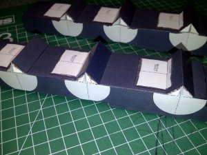
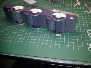
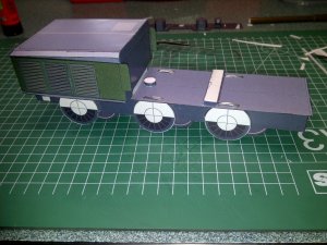
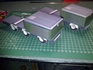
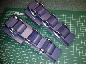
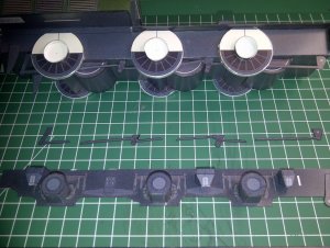
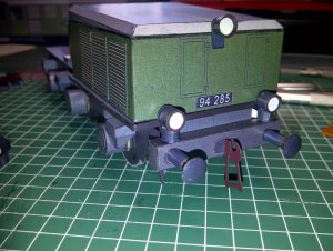
Electric Locomotive E94 »German Crocodile« in 1/38 scale.

DanBKing

Dan the Man
First of all, my many thanks and respect go to Mr Albrecht Pirling, the designer of this perfectly engineered and stunning model.

The electric loco is a German design built by AEG, between 1940 and 1956.
More info here: http://de.wikipedia.org/wiki/DR-Baureihe_E_94 It is in German but Google translate does a decent job!

A pic of the real thing....
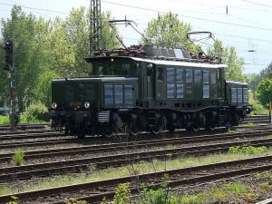
800px-German_Class_194_279.jpg

To be honest, I have never been much of a train freak, but a friend of mine has done something special for me without being asked. I found out later that his favourite train is the E-94. Anyway, after searching and searching on the net to no avail to find a paper model of one, a fellow member pointed me in the right direction, thank you again Chris74.:thumb:
So, I decided I would build it for my friend as a show of gratitude. He also turned 50 during the build process, and I ended up presenting it to him at his birthday bash in front of all his family and friends.
Due to the timeline I was working on, I had to work many long hours into the night, to make sure I got it finished in time for the party. As it turned out I glued the last piece on at exactly 16:30 on the day of the party and the party started at 16:30... That was close!!!:eek: I was only getting about 4 hours sleep a night over the last 2 weeks of the project. (So, if this thread suddenly stops in mid sentence, then you know I have fallen asleep! LOL

Anyway, enough babbling, and on with the build....

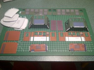
The model came in 21 A4 sheets with seperate basic photographic instructions, well, more of a guide really. All the part identifiers are in German, but once again Google helped out. I printed the sheets on 160 gsm stock. The pdfs actually look scanned, and I dont think they are the originals. I was a bit sceptical about the quality at first, but as you'll see they were perfect.

The loco is divided into 4 seperate sub structures: 1 + 2 are identical twins of the nose and drive train, 3 is the central cab structure, and 4 are the two pantographs, which are models in there own right!!

I started with the 2 nose and drive train structures first. I have only posted one set of photos of these as they are both identical.

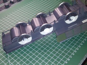
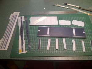
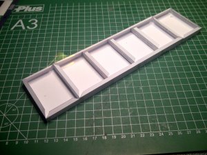
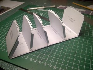
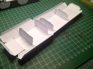
I started with the chassis. The formers are laminated for strength and glued into position. To be honest, nearly 90% of the parts for this model are laminated... :eek: The chassis was then glued up ensuring everything was straight and square.
1.jpg

I then fitted the 'axles'.

2.jpg

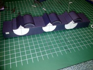
There were no tabs on the curved side walls of the motors but I made my own. Once attached to the motor shell the 3 assemblies were attached to the chassis.
3.jpg

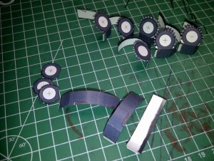
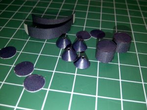
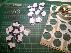
The wheels came in two halves. I laminated these halves to thick card (1,5mm) and cut them all out once dry, using a circle cutter.
4.jpg

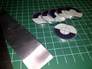
I then lined up the two halves and glued them together. I gave the edges a light sanding to smooth out any imperfections and then lined the edges with thin strips cut from thin aluminium tape, used for ventilation ducting, and no, not duct tape! These strips I then burnished to the wheels with my thumb. It gave the wheels a little more realism.
5.jpg

Because of the limits of uploading, see you in my next post!
 

DanBKing

Dan the Man
Continued...

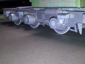
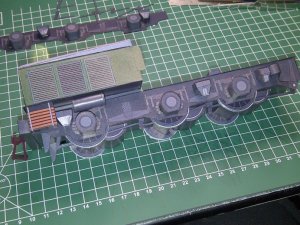
I then attached the wheels to the chassis assembly.

6.jpg

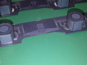
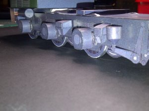
I then cut out the side rails and painstakingly cut out all the springs, t-bars and tensioners and glued them in place on the side rails. Some of these required to be attached onto a cardstock spacer to raise them from the surface. It should go without saying, everything is edge coloured after cutting. I tend to colour everything, if the printed colour butts up to plain white paper, it gets coloured.

7.jpg

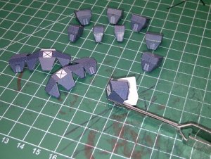
I then started to make the bearing housings. Again, there were no tabs evident on the round end sections, so I made my own to ease assembly.

8.jpg
9.jpg

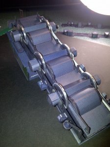
Once complete, the bearing assemblies we attached to the side rails. (all four, from both trucks are shown)

11.jpg

I then made all the sand boxes and fiitted them to the side rails. These also required spacers when attached. You can see these as the white squares in the previous photo.

13b.jpg


I so wish we could multi-upload......:cry:
 
Z

Zathros

Man do you work fast!! I like your technique on the wheels! Very nice! That looks like the nicest Hole cutter I have seen, who makes it? :)
 

DanBKing

Dan the Man
....

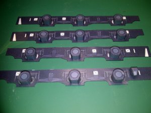
I'm not sure what they are, brake shoes or something, had to be laminated to 2mm cardstock. These were cut out and attached to the side rails butting up against the bearing housings.

16.jpg

I then made up the 2 tiny brake cylinders ready for attachment later.

15.jpg
14.jpg

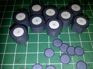
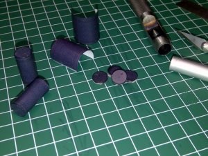
I then made up the two air tanks. I use hole punches to make round shapes. I used these to punch out 2mm thick end caps for the tanks. This aided in assembly, and also kept the shape true.

17.jpg

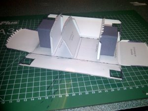
I then made up the 2 upper decks that are double laminated. I then started to put the nose section together and attached this to the smaller deck plate. Before assembly I cut out the six louvre panels and attached them while the nose section was 'in the flat''. Both ends of the box are laminated as well as the support former. I nearly laminated myself to death with this model.sign1

20.jpg
18.jpg
 

DanBKing

Dan the Man
Man do you work fast!! I like your technique on the wheels! Very nice! That looks like the nicest Hole cutter I have seen, who makes it? :)

I wish I could work that fast! The build is already complete, but unfortuantly I did not have the time to post as I went along. So, that means you'll get the whole build posted over then next few days.
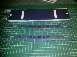
The hole cutter is made by a Chinese company called NT Inc. The model number is C-1500P. Here is a link to their website: http://www.lion-office.com/nt/index.html You can find it under the section Circle/Mat in the Category drop down menu.
 
Z

Zathros

Thanks. Don't worry about posting complete shots. Happy to see whatever you have. Thanks for the info on the cutter and the pics you'll be posting! :)
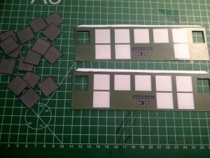


.
 

micahrogers

Moderator "Where am I, and how did I get here?"
Staff member
Moderator
Amazing work as usual. Ya know it was seeing your Discovery that brought me into paper modeling
 

DanBKing

Dan the Man
Amazing work as usual. Ya know it was seeing your Discovery that brought me into paper modeling

Thanks Micah. I am glad I had some influence to bring you into the fold!! (Excuse the pun :mrgreen:) Many happy years of paper modelling stand before you!!
 

DanBKing

Dan the Man
And so we continue......

The swivel and support points that mount on the upper rear deck of the truck, are prepared from laminating thick card, and wrapping these with a thin paper wall. I stuffed punched out scrap card into the rings, to strengthen the circular swivel mounts

IMG-20120824-00178.jpg

The mounts were then attached to the rear decks.
I glued the rear deck and the front deck/nose assembly to the chassis.
The little 'wings' on the rear of the nose, need a piece laminated to the back, to give it colour too.
And I didn't make a mistake, the wheels are meant to stick through the deck like that!:cool:

IMG-20120902-00302.jpg

Before the side rails are attached, the wheels need spacer rings attached.
You can see them in this pic of the two trucks, both completed to the same level. (I started to see double after a while, but that might of just been the beer!! :rolleyes: )

IMG-20120907-00365.jpg
IMG-20120907-00367.jpg


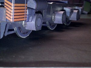
All the pre-laminated brake fittings were carefully cut out and sorted into the correct order, and then glued in position between the wheels and axle/motors. Very delicate work, all being edge glued into position. The cutting took an age..... You can also see the pre-assembled side rail, ready for mounting in the next section of the build.

IMG-20120907-00383.jpg
IMG-20120907-00397.jpg
 

DanBKing

Dan the Man
Next, the rear plate was laminated and mounted, and the front rail that holds the two front lights and the 2 'bumpers' were attached to the chassis.
These need to be in position before the side rails are attached. The side rails were attached by gluing them to the spacer rings and edge gluing them to the front rail and rear plate. I also added a few dabs of glue along the top edge to hold it securely to the bottom of the rear deck.
Once the side rails were in place, I attached the brake cylinders and air tanks that I assembled earlier. I also assembled the oil cooler that fits on the front left of each truck.
Here are a few pics of the completed side rail assemblies.

IMG-20120907-00409.jpg

IMG-20120907-00411.jpg

IMG-20120907-00415.jpg

IMG-20120907-00387.jpg

IMG-20120907-00401.jpg


Back in a bit.... :wave:
 

DanBKing

Dan the Man
The twins are born!

Getting to the end of the assembly of the two trucks now.
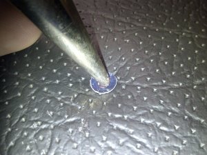
I made up the bumpers and attached them to the front rail. My trusty modern wine bottle stopper, which I use as a cone mandrel (See my Discovery build), has a nice rounded point. I used this to shape the bumber plates, by pressing down on the plate while making circular motions with the point, with a piece of backed foam underneath. This technique worked well, as you can see.. :thumb:

IMG-20120902-00309.jpg
IMG-20120908-00429.jpg

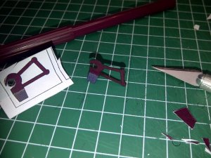
I then laminated and cut out and mounted the linkage. (I screwed up the first one on the first cut, as you can see... wall1 )

IMG-20120902-00306.jpg

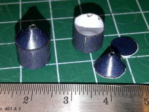
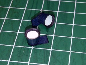
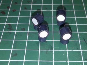
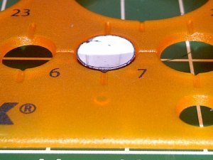
I then made up the lamps for the nose and the two on the front rail. I use a circle template to keep small tubes like the lamps, perfectly round..

IMG-20120908-00438.jpg
IMG-20120909-00509.jpg
IMG-20120909-00496.jpg
 

DanBKing

Dan the Man
The side of the front deck needs a thin strip of card wrapped around the side edges to finish it off.

IMG-20120907-00416.jpg

Here is a pic of the completed nose section.

IMG-20120909-00511.jpg

And the trucks are done!!!!!!!!!

Tomorrow we'll start on the centre cab section.

Nite nite! :wave:
 

DanBKing

Dan the Man
And, now for the Middle Bits..!

With the two trucks out of the way, I progressed onto the next stage....
The middle section, which is sub-divided into 5 assemblies: The chassis, main body shell, two drivers cabs, and the roof structure and associated sub-assemblies (excluding the pantographs.)

As with the trucks, I started with the chassis. Quick and simple, after laminating everything as usual... :rolleyes:
I cut all the other relevant parts, including the two deck plates for the drivers cabs, and the main deck plate. All, of course, laminated.....
The flaps along the sides of the center deck plate need to remain un-laminated. This is where the main body walls attach to later...
The side rails and associated edging strips were also cut out.

IMG-20120818-00011.jpg


IMG-20120818-00013.jpg
IMG-20120819-00047.jpg

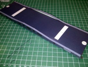
Once the chassis had dried, I attached the side rails and edging strips.
(This pic is looking at the bottom of the chassis. You'll also notice the corresponding swivel and support mounting points, that marry up with the two sets of mounts that were attached to the trucks earlier.)

IMG-20120828-00235.jpg

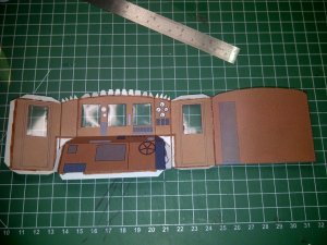
The parts for the body shell and cabs, were cut out and prepared, including the parts for the interior of the cabs.
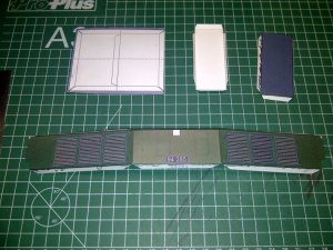
The louvre panels were attached to the main body walls, 'in the flat', as before. One thing I noticed, luckily, right in the beginning, is that the louvres have a definate top and bottom, they have to be put on the right way up, (or down!) Think of how light falls on a louvre blind........

IMG-20120819-00019.jpg
IMG-20120819-00023.jpg
 

DanBKing

Dan the Man
The end walls and internal walls were attached to the main deck plate.

IMG-20120820-00069.jpg

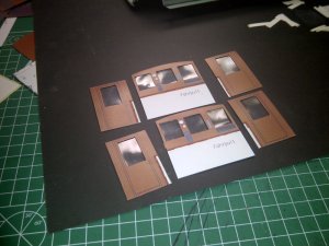
I attached the side walls, made up and attached the two transformers to the interior. I did not box up the overall assembly yet, as the four windows in the side panels still have to be glazed......

IMG-20120821-00082.jpg

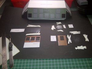
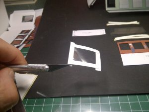
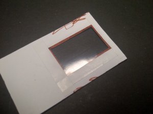
I made templates that were about 1 - 3 mm bigger than the window openings, the size depended on the available space! I cut the glazing from clear page protectors. I cut thin strips from address labels which were used to attach the glazing to the inside of the window openings.

IMG-20120821-00095.jpg
IMG-20120821-00106.jpg
IMG-20120821-00111.jpg

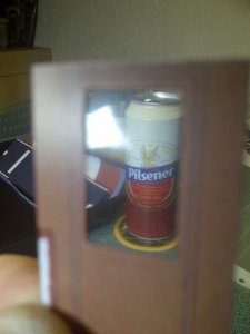
Nice view through the drivers door window........ :mrgreen:

IMG-20120821-00116.jpg
 

DanBKing

Dan the Man
The center section grows.....

Everything is now glazed. The 'glass' looks a little wrinkly in the pic, but that all straightens up when the interior is glued to the outside walls.

IMG-20120821-00128.jpg

The inside walls are glued to the outside walls and any white space between, coloured in. It is imperative that you DOUBLE check where you glue the inside panels, in relation to the fold lines in the outside walls. If you dont get it right, the body shell won't go into the final shape cleanly.
I started with the center panel, ensuring the distance from the fold line was exactly the same on both sides. I then worked outwards from this panel on both sides. I just coated the inside panels with glue, placed it LIGHTLY in position, and folded the shell into the correct shape, and gently moved the inside panel forward, to butt up to the previously affixed wall. Also, it is important that you TRIPLE check your window opening alignments, from both inside and out. (Also, before you glue, make sure you have coloured around the edges of the frames first!!) When all is correct, open up the cab shell again, lay it flat, and press the inside panel firmly home.
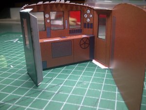
The drivers console is glued into position along the top edge only.

IMG-20120821-00132.jpg

The cab shell is the glued into shape around the console. I used the marking on the floor plate as a guide for positioning, while gluing up.

IMG-20120821-00137.jpg

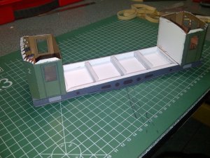
Once dried the shells are glued to the deck plate and then this assembly is glued to both ends of the chassis.

IMG-20120828-00245.jpg

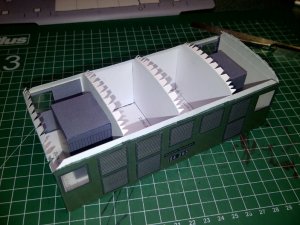
The main center section is boxed up and the interior strengthening, and decorative panels are laminated :)rolleyes:) in place next. Double check your measurements, before cutting the grey panels around the windows!

IMG-20120828-00211.jpg

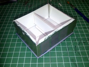
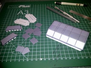
The box section for the roof is made up in preparation for mounting to the roof later. Note: There is no need to score and fold the center line of this, as the roof of it is flat.

IMG-20120820-00072.jpg
 
Z

Zathros

Nice! If you make a wheel (the one that looks like a steering wheel) the print will look like a shadow. :)
 

DanBKing

Dan the Man
Put a lid on it!!!

We move on to the roof, which is laminated. Make sure that both sides of the two pieces are aligned (and cut out,) exactly right!!!
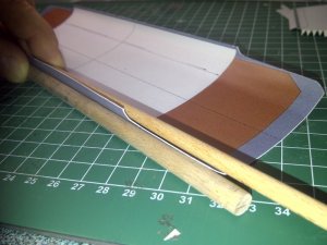
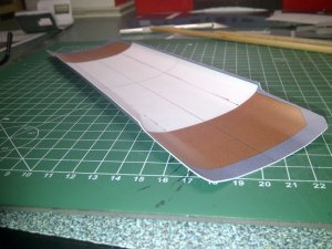
The roof needs to be formed into its final shape before gluing anything to it, or gluing the roof itself into position on the body shell. The roof has three distinct planes, along its length: A gentle curving section from the center to the outside edges of the white boxes (where the pantograph mounts attach,) From here it is a flat sloped plane, up to the edges of the roof which are curled sharply downwards.

I measured everything up carefully, using the cab sections and center sections as reference. For the middle plane I also used the box section that fits to the roof as reference for the curve. I created the curve by placing the roof, top face down on an old mouse mat and used a large diameter dowel as as fulcrum for the creation of the curve. Gently raise the edge of the mat to form the curve. Be careful, do this in gradual stages, so as not to crease the card. Change the position of the dowel regularly to form the final curve, but dont go over the section that is flat between the edge of the roof and the curved section. (You can see my reference lines drawn on the inside of the roof, for this purpose.)
The flat sloped section needs no shaping.
The edges along the section of roof, that attach to the center section of the cab, are the only edges that are heavily curved downwards. I used two dowels to forms these. Again, IN GRADUAL STAGES!!!!!!

IMG-20120820-00063.jpg

IMG-20120820-00057.jpg

Once the roof is in the correct shape, I first glued it to the center cab section, (but not the drivers cabs yet, as the center section is not yet attached to the chassis!) by gluing one end panel to the roof first. Once this was dry, I gently raised the roof(!) and glued up the tabs on the support sections and the opposite end section, BUT NOT THE TABS ALONG THE TOP OF THE CAB SIDES, (you'll see why in a minute,) and glued the roof into final position, making sure the end sections line up with the demarcations on the roof.

Next, I attached the pre-assembled box section to the roof, ensuring the roof fit snug to the curved edges of the box.

IMG-20120828-00217.jpg

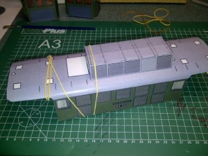
I wanted to make sure that the edges of the roof, remained glued all away along the top edge of the cab walls, remained straight and correctly curved. I brain stormed with my cat over this problem, and then had an idea how I was going to hold everything correctly while gluing.......
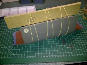
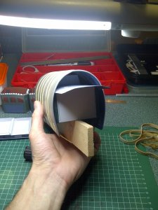
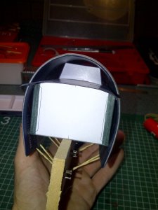
I got together all the bits I needed for the next operation.... Two flat pieces of wood, plenty of elastic bands, the trusty old mouse mat, and a flat wide paint brush........ I loaded the brush with a reletively slow drying glue, gently eased up the edge of the roof and ran the brush along the join tabs at the top of the cab walls, ensuring everything was coated.

The next pictures should hopefully explain how I did the next bit!!

IMG-20120828-00221.jpg
IMG-20120828-00230.jpg
IMG-20120828-00233.jpg


See ya next time. :wave:
 

micahrogers

Moderator "Where am I, and how did I get here?"
Staff member
Moderator
:-o
Ingenious use of tools!
I would have never thought of that.
 
Top