

Building Beeg Boy.... (LOTS of pictures)
- Thread starter doctorwayne
- Start date
You are using an out of date browser. It may not display this or other websites correctly.
You should upgrade or use an alternative browser.
You should upgrade or use an alternative browser.
I'm just curious about the fact that the cab is a different black than the boiler. Did the prototype use a different black for the cabs on all of their steam engines or just on this one?
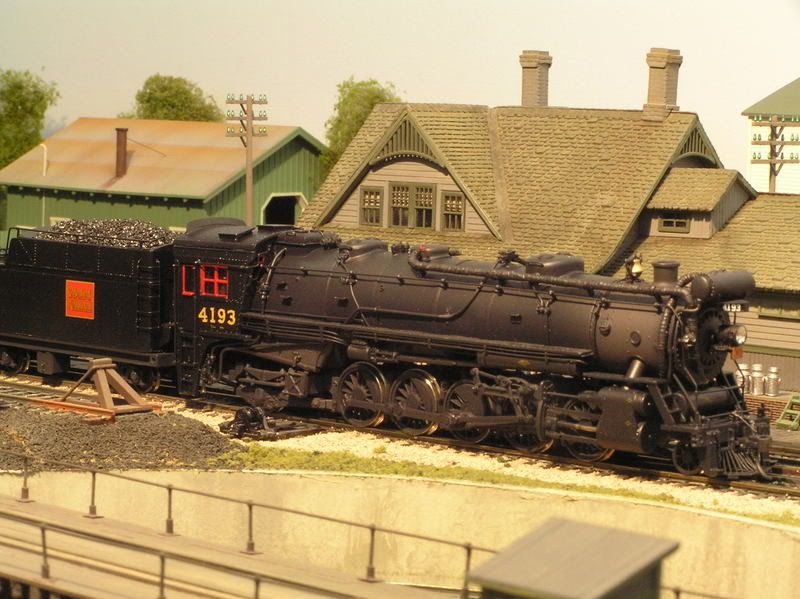
I don't think so, Russ: in fact, near the end of steam, most locos that got painted looked like dip-jobs, all glossy black. When painting steam locos, I generally use four different versions of "black", with the cab and tender being the darkest; the boiler and smokebox front, along with the tender deck, pilot, cylinders and appliances get a lightened version of a similar colour; and the frame and running gear of both loco and tender an even lighter version. The smokebox and firebox are done with a black to which a lot of brown and grey have been added, along with some red and/or orange. I also use various mixes of clear finishes on different parts of the loco, ranging from a fairly high gloss on the cab and tender, to less glossy and almost flat finishes elsewhere, with the firebox and smokebox getting none at all. In person, the range of colours is fairly subtle, giving the impression of a recently-shopped locomotive, and is a first step in the weathering process. For some reason, some of my photos have a purplish cast to them, although my two pictures of the loco on the bridge are fairly close to what you'd see in real life.
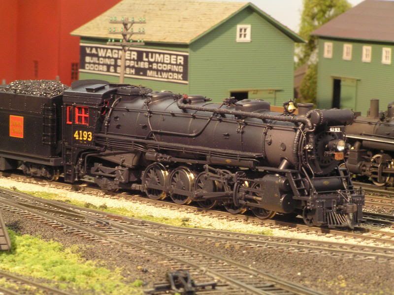
Mister Nutbar's photos are generally clearer than mine, and have a greater depth-of-field - unfortunately, to gain that depth-of-field, the camera is set at f8, stopping down the lense enough that we had to use a portable "trouble light" as "Mister Sun". While this lightened things up considerably, it also seems to have over-emphasised the differences in colours. The picture of the loco passing Wagner Lumber is close to what you'd see if you were here.
Wayne
For the scanned photos, I usually use the colour correction options available while scanning. The purple camera pictures are a puzzle, though, as I set the camera for the light being used (fluorescent on the layout, fluorescent or incandescent in the paintshop, depending on which workbench, and incandescent on my modelling workbench). The camera seems to reset itself if I take too long between shots, and will shut off completely after 10 minutes of inactivity, requiring a completely new set-up - this is with the camera running on an adapter, not batteries, but there's no way to override it! 
I think I'll have to wait 'til those times when Mister Nutbar comes to visit, then take my pictures with his camera.") :-D
:-D
Wayne
I think I'll have to wait 'til those times when Mister Nutbar comes to visit, then take my pictures with his camera.
:-DWayne
This raises another question in my mind, Wayne. I remember seeing steam when I would ride with my dad on his truck to load watermelons in the 1950's. He sold that business in 1955, and if I remember correctly steam had pretty much disappeared by 1953 or so in the California Central Valley. I don't remember a lot about the steam engines I did see on trains in the early 1950's, I was just a little kid at the time. Did the steam engines in daily use perhaps weather the way you are painting them because the heat off the boiler and firebox tended to bake a glossy black to flat faster than the color would change on a relatively cooler cab?
Well, from the pictures that I've seen of steam locos, especially those in Ian Wilsons books on the CNR in the '50s, that's what it looks like to me. Of course, some locos were pretty dirty all over, but those that appear to be well-maintained had cabs and tender sides that definitely appeared more glossy than the boiler, cylinders, etc., and the paint also appeared to be darker. I think that the heat must've played a role in this, as it doesn't take long for the smokebox and firebox (not lagged on most locos) to lose their sheen. Nowadays, even if I were painting a loco that was to be heavily weathered, I'd use multiple colours (possibly lightened just a bit) and multiple variations in the gloss of the finish coat in the paint job, then weather over top of that.
I don't recall too much about the steam engines that I saw as a child, either - they were pretty common, whereas a new diesel was a big deal.
 ops:ops:
Wayne
I don't recall too much about the steam engines that I saw as a child, either - they were pretty common, whereas a new diesel was a big deal.
ops:ops:Wayne
That's amazing work DR Wayne. Thanks for explaining your painting process to us. It will come in handy for me in the future.
The closest steam engine (operating) that we have is a ex-CPR 2-8-0 operating in the Kettle valley steam train in Summerland. It has weathered almost exactly as Wayne has stated with the cab and tender staying glossy, and the boiler flatening slightly and the smokebox completely flat, probably due to heat.
Could you give use some infor on the tender herald? I notice it's straight but on many CNR engines it's 'tilted' and on others there is a round herald. One model I've seen simply has "Canadain National" in white across the tender. Are all these correct or do they show different eras of livery?
CN Nut....You gotta be the luckiest dude this side of heaven.....!!! Great pics of a marvelous engine....
Doc....Could you elaborate a little on the "plumbing" for the feedwater heater..?? Thanks...
Doc....Could you elaborate a little on the "plumbing" for the feedwater heater..?? Thanks...
CN Nut....You gotta be the luckiest dude this side of heaven.....!!! Great pics of a marvelous engine....
Doc....Could you elaborate a little on the "plumbing" for the feedwater heater..?? Thanks...
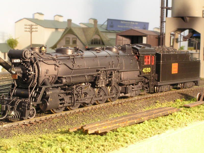
hello everyone---Gus,I am lucky to have such a good friend---for those of you who have followed my threads,you must realize that Wayne deserves all the credit when it comes to my collection ---I can honestly say that Wayne has provided the inspiration for me in this wonderful hobby---here's another shot of 4193 at her home terminal---thanks again

That's amazing work DR Wayne. Thanks for explaining your painting process to us. It will come in handy for me in the future.
The closest steam engine (operating) that we have is a ex-CPR 2-8-0 operating in the Kettle valley steam train in Summerland. It has weathered almost exactly as Wayne has stated with the cab and tender staying glossy, and the boiler flatening slightly and the smokebox completely flat, probably due to heat.
Could you give use some infor on the tender herald? I notice it's straight but on many CNR engines it's 'tilted' and on others there is a round herald. One model I've seen simply has "Canadain National" in white across the tender. Are all these correct or do they show different eras of livery?
Thanks, Glen, both for the compliment and for the comment on the effects of weathering.
Back when the CNR was formed, locos had "Canadian National" spelled out in white on the tenders. In the late '20s, the "wafer" herald was adopted, based on one used by predecessor Grand Trunk Railway, which used a similar herald on its timetables since 1898, and also by another predecessor, Grand Trunk Pacific, since 1909. It was tilted at a 9 degree angle, and centred either on the tender side or centred on the coal bunker area - I can't see a pattern to which locos got which location, but different shops probably determined where they put it.
In the mid-'50s, the "wafer" went from the 9 degree tilt to a position, usually centred on the coal bunker, which was square: ie - not tilted. Some locos, like the 4193, also got a version of the wafer that had black shadow lining around the lettering. Earlier versions were red and yellow only, with no shadow lining. In 1954, the circular "maple leaf" herald was introduced, probably to coincide with the introduction of the black, green, and gold paint scheme on the new lightweight passenger cars that the CNR was receiving at the time - these cars were also adorned with the same circular herald. Most, if not all, of the locos receiving this herald seemed to be ones primarily in passenger service.
Doc....Could you elaborate a little on the "plumbing" for the feedwater heater..?? Thanks...
Gus, rather than send you back to dig through the pictures in the original post, I'll re-post a couple:
This is the fireman's side of the loco:

Of the three pipes extending forward from beneath the cab, the upper one is the water delivery pipe from the tender. It takes water to the cold water pump, which in turn delivers it, via the large diameter pipe, to the heater "bundle" at the front of the loco. The small pipe on the upper right side of the water pump is the live steam line from the loco's turret (itself located atop the boiler, immediately in front of the cab). This pipe runs mostly under the boiler lagging, appearing just above the raised portion of the running board over the pumps. It supplies the steam which runs the water pump. (The other line coming out from under the lagging is the steam line to run the air pump.)
The other small pipe, exiting the upper left side of the water pump is the exhaust steam pipe - it too goes under the lagging, also to the heater bundle.
Moving towards the front of the loco, the cold water pipe passes through a clean-out, then enters the lower connection on the end of the heater bundle. (The inside of an Elesco feedwater heater is a series of tubes, filled with steam, that raise the temperature of the cold water by about 160 degrees F.) The heated water then exits the upper connection on the heater end and travels, via the lagged horizontal pipe above the cold water line, to the boiler check valve. (On this loco, the top-feed check valve can also be fed cold water by an injector-operated pipe on the engineer's side of the loco - this is a back-up should the fwh pump fail.)
The large, vertical, lagged pipes (one on each side of the smokebox) feed steam, exhausted by the locos cylinders, from the steam chest to the heater bundle.
Moving to the other side of the loco:

The other lagged steam line from the cylinders to the heater bundle can be seen. Immediately in front of it is a smaller pipe, exiting the bottom of the heater end cap, and heading in behind the air tank on the pilot deck. This is the condensate line (for the steam that has become water after doing its heating duties). It loops around under the boiler, passing through an oil separator, then returning the water to the tender. The other end of this pipe can be seen in the first photo - it appears from behind the water pump and is the lowest of the pipes as they disappear behind the cab steps.
Also visible here, on the engineer's side, is the cold water pipe that comes from beneath the cab, along the boiler to the top feed check valve. (Right behind the front sand box.)
Finally, a top view:

The two small lines which appear from under the boiler lagging, and run, on either side of the stack, to the heater bundle, are exhaust steam lines - one from the water pump and one from the air pump seen in the first photo. They also contribute steam to the heating process.
It was estimated that this type of feedwater heater, which used from 12% to 16% of the exhaust steam available from the cylinders, (leaving plenty available to maintain the draught) resulted in a fuel saving of nearly 15%. In addition, by reclaiming the condensate, an additional 1500 gallons of water (using a 10,000 gallon tender) is saved.
I hope this explanation is of some help.
Wayne
Thanks Doc....As I understand it then (finally), the feed water heater has 4 sources of steam (heat): 2 from cylinder exhaust, and 2 from air and water pump exhaust. It's "product" (hot water) goes to the cold water check valve. I hope I got it right....I presume the cold water check valve injects the hot water into the boiler..? Thanks for the info.
Almost right, although I should have stated it more clearly. This loco has a top feed check valve, which can be supplied from either the feedwater heater (with hot water) or from the injector on the engineer's side (which supplies cold water directly from the tender).
On a loco with no feedwater heater, there would also be an injector feeding cold water, from the tender to the check valve, on the fireman's side.
Either system could also use separate check valves on both sides of the boiler - with a feedwater heater, usually the check valve on the fireman's side is the one supplied from the fwh.
Wayne
I have a couple more questions:
Injectors, as I understand them, use live steam injected into the cold feed water (along with a series of venturis that I have yet to fully grasp) to give it the energy to overcome the check valve / boiler pressure. Do you have any idea how much this raises the feedwater temperature?
Ah, this is new to me. I always assumed the condensate was "exhausted" onto the roadbed. Is this recovery common in North American railroads (I've read of condensate recovery in arid areas of South Africa)?
I apologize for the further thread diversion!
Matt
<snip>
(The inside of an Elesco feedwater heater is a series of tubes, filled with steam, that raise the temperature of the cold water by about 160 degrees F.)
<snip>
(On this loco, the top-feed check valve can also be fed cold water by an injector-operated pipe on the engineer's side of the loco - this is a back-up should the fwh pump fail.)
Injectors, as I understand them, use live steam injected into the cold feed water (along with a series of venturis that I have yet to fully grasp) to give it the energy to overcome the check valve / boiler pressure. Do you have any idea how much this raises the feedwater temperature?
<snip>
This is the condensate line (for the steam that has become water after doing its heating duties). It loops around under the boiler, passing through an oil separator, then returning the water to the tender.
<snip>
Ah, this is new to me. I always assumed the condensate was "exhausted" onto the roadbed. Is this recovery common in North American railroads (I've read of condensate recovery in arid areas of South Africa)?
I apologize for the further thread diversion!
Matt
It has weathered almost exactly as Wayne has stated with the cab and tender staying glossy, and the boiler flatening slightly and the smokebox completely flat, probably due to heat.
You might also have been observing a graphite based "paint" in those two areas. This finish was an oil and graphite mix used in place of paint in very hot areas (paints weren't yet up to the task), was flat and can very in color from a dull silver to a very dark gray, depending on how it was mixed.
Matt
I have a couple more questions:
Injectors, as I understand them, use live steam injected into the cold feed water (along with a series of venturis that I have yet to fully grasp) to give it the energy to overcome the check valve / boiler pressure. Do you have any idea how much this raises the feedwater temperature?
I looked through my copy of the Locomotive Cyclopedia and didn't see any mention of water temperature increase by live steam injectors, lifting or non-lifting, so I'd assume that any heating effect was negligible. However, the book did note that the Elesco exhaust steam injector also acts as a feedwater heater (it was often called the poor-man's fwh), although it failed to cite the actual temperature increase. It did note a corresponding fuel savings of 8% to 10%, so the heat increase must've been significant.
Here's one on a CNR Mountain (by the 3rd and 4th drivers - you can see the steam delivery pipe running from the cylinder area, above the drivers, to the injector:

The book also noted that the condensed steam resulted in a 12% savings in water, as it was returned to the boiler. This indicates to me that this was an "open" system, like the Worthington Type E fwh, in which the steam is in direct contact with the water.
Ah, this is new to me. I always assumed the condensate was "exhausted" onto the roadbed. Is this recovery common in North American railroads (I've read of condensate recovery in arid areas of South Africa)?
Matt
Well. I think that the only reason that it was collected is because it was already captured for use in the fwh - it made sense to keep it for re-use afterwards, rather than just dump it. Conversely, installing a condenser on a non-fwh-equipped loco probably didn't offer enough monetary incentive to bother with - they just let it go up the stack.
Wayne
I looked through my copy of the Locomotive Cyclopedia and didn't see any mention of water temperature increase by live steam injectors, lifting or non-lifting, so I'd assume that any heating effect was negligible. However, the book did note that the Elesco exhaust steam injector also acts as a feedwater heater (it was often called the poor-man's fwh), although it failed to cite the actual temperature increase. It did note a corresponding fuel savings of 8% to 10%, so the heat increase must've been significant.
...
The book also noted that the condensed steam resulted in a 12% savings in water, as it was returned to the boiler. This indicates to me that this was an "open" system, like the Worthington Type E fwh, in which the steam is in direct contact with the water.
Wayne and all others,
I have read with high interest your explanations to working of steam loco components.
I worked more than 40 years ago while I was a young man in a loco shed as a steam engine repair man (or mechanic) and loco shed foreman. Loco mechanic was the need in order to be an engineer at a later time and before you must know how a steam loco will work and you must work as fireman likewise before you could start a carrier as engineer. Steam loco mechanic was an own profession with a training time of two years (in East Germany). So I understand very well all your explanations to feed water heaters and injectors and I see also the differences to German locomotive techniques however they are not very significantly.
However I would write a small addition about injectors because a small question is not cleared.
An injector works like a system of jets which get their power by the hot steam which is streaming through the jets. The cold water from the tender will be sucking in one of the cambers and cold water and hot steam with boiler pressure will be mixed together. The fresh steam coming from the boiler has a temperature around 390 degrees (F) – sorry I must this write here exactly because we measure in degree Celsius here in Europe. The temperature of feed water after it has mixed with the steam has a temperature of 170 to 180 degrees (F) and all of steam is condensed to water again.
The lost energy of the hot steam by condensing raised the pressure of the feed water and that is the most important working aspect of an injector. The feed water gets so by changing the energy in injector a higher pressure then it is in the boiler and so the feed water can be pressed through the feed water check valve in the boiler.
The warming up of the before cold feed water is a need in order to save the boiler against tension and destroying.
So you have two aspects using an injector. One is that steam with boiler pressure und using a jet system is changed to water with a higher pressure than the steam has had before and equally the cold water of the tender gets a middle high temperature so that the boiler will not get damages.
I hope again that my English will be readable and that you can understand the sense.
Bernhard
Good job Bernhard
Bernhard I read through your explanation and it seems to be perfect.
I operate 1:1 steam traction engines. One of the long answer questions for the operators examination was to describe how a steam injector works using your own words. This is one of the most complex parts to understand on a steam engine but yet one that uses simple physics laws to inject unpressurized water into a pressurized boiler.
I have attached a picture taken from
Steam & Engine of Australia - Steam Simply Explained - Water Injector

This is a Penberthy injector. They were very common on Case steam traction engines. By examining the picture and its captions you should be able to get a visual understanding of what Bernhard explained in the last post.
I hope this helps someone out. I don't have a lot of knowledge about steam locomotives but I do understand Traction engines fairly well, so if my picture is vastly different from the way steam locomotive injectors work then feel free to chime in.
Bernhard I read through your explanation and it seems to be perfect.
I operate 1:1 steam traction engines. One of the long answer questions for the operators examination was to describe how a steam injector works using your own words. This is one of the most complex parts to understand on a steam engine but yet one that uses simple physics laws to inject unpressurized water into a pressurized boiler.
I have attached a picture taken from
Steam & Engine of Australia - Steam Simply Explained - Water Injector
This is a Penberthy injector. They were very common on Case steam traction engines. By examining the picture and its captions you should be able to get a visual understanding of what Bernhard explained in the last post.
I hope this helps someone out. I don't have a lot of knowledge about steam locomotives but I do understand Traction engines fairly well, so if my picture is vastly different from the way steam locomotive injectors work then feel free to chime in.