N&W CF Caboose - AMB (IMAGE HEAVY!)

Fluesheet

Member
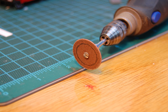
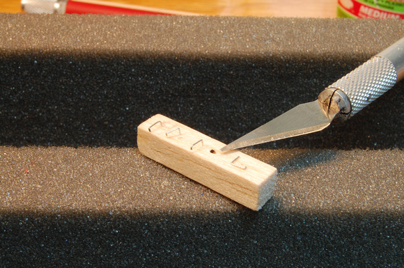
Thanks as always for the advice doctorwayne. I've learned the cut off wheel trick after damaging a good pair of xuron cutters (doh). School of hard knocks, I suppose - I simply didn't expect the stuff to be as hard as it was. Since that photo was taken I've squared that "pinch" from the side cut with a cut off wheel.

For the lighter gauge stuff (up to .015") that's *not* steel, I've had good luck with scissors. The bypass cut prevents the little burrs that sidecuts produce. I'll have to try the Xacto trick for the bigger stuff.

Sarge; I'm glad to be able to contribute to the "body of knowledge" on this board. I know I've benefited from other folks contributions (doctorwaynes above being the most recent example!).

Fluesheet
 

nkp174

Active Member
I've dropped music wire from my supply box...except for truss rods...due to the additional difficulties in bending it. I also damaged a nice cutting tool on music wire. I was a bit surprised because the needle nose pliers I use to cut my guitar strings have never been harmed by music wire.

It is looking very, very nice.
 

Fluesheet

Member
End Beam

Before doing any additional detail work on the ends, I painted the platform, end beam and steps Polly Scale Engine Black while they were still easy to access.

Next was some end beam detail. The bolts are Tichy part number 8016 and represent 1 3/4" nuts / 2 1/2" washers. I don't know if this is the right size, but they look pretty good. The styrene represents a part that I don't know the name of, but whose intention is to tie the draft gear and end beam together. I made this from .010" thick styrene cut .050" high by .345" long (about 4.5 x 30 scale inches). This looks very nice painted, but that pic comes later.
p442517994-3.jpg


Next I created the platform end railing from a re-formed wire part in the Detail Associates #550 detail kit. I will not take this route for the next kit; the thinner material (.0125" dia) was harder to work with than the .015" brass wire used for the car body grabs and the end result looks too dainty.

Before
p482598113-2.jpg


After
p524258311-2.jpg


Corner posts were cut, bent (curve at the bottom) and CA'd in place. The prep work made this a breeze. The end railings were then CA'd into their holes in the end beam and butt-joint CA'd to the corner posts.
Also in this next picture is what will become the bracket to hold the car-end wheel spray shields in place. These shields were intended (in real life) to keep the muck thrown up by the wheel treads of the car in front of the caboose off the end platform.
The "bracket" is simply a strip of paper about .025" wide CA'd to the floor (I bent a small "foot" to increase contact area) and to the railing on top. I actually wrapped the strip around the railing and glued it to itself on one end; looks good, but that was exhausting (these are small parts!), so I skipped the wrap on the other end.
The piece of paper lying on the platform was a template to ensure even spacing of the strips on all four corners.
p817302154-3.jpg


This last image shows the shields in place. These are also paper, about 2' wide by 28ish" tall (.270" x .320") fastened to the brackets with white glue. Once that dried, I dabbed thin CA onto the shields and brackets. The paper readily absorbed the CA and the end result was nice and rigid. Using paper allows the detail to be very thin - about .003" (1/4" scale), avoiding that "clunky" look that thicker details can have.

p539968154-3.jpg


I apologize for the wordy posts!
 

doctorwayne

Active Member
Lookin' good, Matt! :thumb::thumb: That's an innovative idea for those splash shields, too.

I apologize for the wordy posts!

The pictures are great, but a good written explanation of the photos is a real asset, too. I'm the one that does "wordy". :rolleyes:;):p:-D

Wayne
 
Outstanding work! Those platform shields really add a distinctive touch. Again, thanks for sharing and I must echo Wayne, as one whose own picture threads are also wordy, thanks for the explanations. [BTW, Wayne, why so brief? Only kidding.] Keep sharing your progress!
 

nkp174

Active Member
Fluesheet, I'll need to add those same panels to my DSP&P waycar...so thanks for pioneering it for the rest of us :)
 

Fluesheet

Member
Miscellaneous Progress

I have several remaining details for the ends; ladders, brake wheel detail, "cut" bar (uncoupling lever), detail to connect the gutters to the corner post (which server as downspouts), and possibly poling dimples.

I used the ladder from the Details Associates kit. My first step was to thin the ladder side rails slightly at the bottom and to remove the bottom most rung. The thinning would allow the ladder to overlap the end beam (as in the prototype) without appearing too thick, the rung removal allowed me to use what was the rung bolt detail to represent the bolts holding the ladder to the end beam.

To thin the sides, I located the ladder so that it had the appropriate amount of overhang, and marked that spot with an x-acto. From that point down I removed about half of the side rail thickness (they started about .015" thick, ended up @ .008") using an x-acto and file.

p801875363-3.jpg


A side benefit of creating this "step" was easily repeatable location of the ladder while trimming the top of the ladder to length, as well as moving the ladder slightly further in from the roof end. .008" doesn't sound like much, but it made a favorable visual difference.

Since my hands aren't terribly steady, I'll use crutches whenever I can. In this case, my crutch was a shim to lay the top of the ladder against while I applied the glue. The overlap on the bottom served that purpose there. The shim is simply some .020" styrene, with shallow channels filed at the width of the corner posts on which the shim would be resting. This accomplished two things: it prevented the shim from moving around as I shakily laid the ladder on it, and also made it effectively thinner, which it needed to be to have the ladder be vertical. I used CA medium to attach everything.

p638167279-3.jpg


Lastly, painted - it's looking pretty good! On to weights and end brake detail!

p1005499128-3.jpg
 

Fluesheet

Member
Weights... (that I forgot)

Yep, forgot to put any weight into the carbody before fastening it all up. Doh. :eek:ops:

I had a couple ideas on how to add weight, the easiest being to dribble some #7 1/2 birdshot into the open window where my conductor is sitting. The problem with that is that birdshot is round, therefore it rolls. Plus, what's the point of putting in interior detail and having the equivalent of a couple hundred melons rolling around my 1:87 floor?

Short story long, I chose to dig a slot into the center sill and insert some sheet lead.

Step one was to determine how deep I could go before having to worry about my crew stepping into holes in the interior floor. The total thickness of the floor and the two pieces that make up the center beam was just greater than .040". I pencilled a line on a dremel cutoff wheel exactlyish .040" from the edge...

p994215056-3.jpg


...and carefully cut two slots in the center sill between the bolsters. It's worth noting that an abrasive cutter is not the most efficient wood cutting implement, but in this case, that was probably a good thing as it allowed the work to proceed slowly enough to be easily controllable. I also cut down the remaining "island" of wood as much as possible with the cutoff wheel, then finished off with a 1/8" router bit to square everything up. Hard part done.

p592386253-3.jpg


The last steps were to cut the lead strips, insert and secure them (medium CA) and do some touch up filing and puttying to level everything up / fill cracks.

When all was said and done, I'd added .2 oz to the car. Currently with trucks it's going to be around 1.6 oz, so depending on how it tracks, I may end up thinking up something else.

p954039846-3.jpg

p874214967-3.jpg


When all was said and done, I'd added .2 oz to the car. Currently with trucks it's going to be around 1.6 oz, so depending on how it tracks, I may end up thinking up something else.

Next, cupola grabs and gutters.
 

Fluesheet

Member
After some time off, I made some more progress on the model this week. I chose to start on the gutters as grabs had me a little worn out.

The gutter is simply a .030x.030" piece of basswood with one corner rounded off to give the impression that it was channel shaped and mounted at a slight angle to allow drainage toward the corner posts. Since the gutter is liable to get touched a LOT over the model's lifetime, I was a little hesitant to rely on CA glue alone (the facia board was already painted, so wood glue wouldn't have been effective - live and learn), so I decided to "pin" all six gutters in place, in addition to using CA.

The pins are .015" brass. The following two photos show the pins with and without the gutter installed.
p262821601-3.jpg

p76760317-3.jpg


Next were the cupola top grabs. These came straight from the Detail Associates kit - I only had to bend an additional 90 degree bend on each of the legs to insert into holes drilled into the sheathing.

p176468729-3.jpg


The prototype caboose also had a support grab right at the corner that went around the soffit and into the sheathing. I put off bending and drilling these for days. They're just so darn small! The first image shows the supports, the second shows one installed left side of the coupola. Prior to final installation, I painted all of the supports to save the tedium of keeping the grab paint off the sheathing. Note that one bend (the short one) is also flattened to allow a lower profile connection to the corner grab itself (attached w/CA)

p744635429-3.jpg

p994841574-3.jpg


The support is CA'd to the corner grab and also into the sheathing. The cupola corner grab itself has short "legs" that go into the sheathing, but no adhesive is used. Spring action is more than sufficient.

Lastly, this photo shows all cupola corner grabs installed as well as pinned and painted lower gutters (I've also dug a small channel into them, which is the reason they look a little rough right now). The small dots on the gutters are putty covering the slightly recessed pins. Cupola gutters and their downspouts still need to be mounted.
p555108363-3.jpg


Matt
 

Fluesheet

Member
Downspouts and couplers and trucks, oh my.

I've got to get a move on - Tetters has handlaid an entire yard in less time than this caboose has been in the project phase! Nevertheless it's getting tantalizingly close:

A couple pages back I talked about lighting; the axle wipers I purchased to energize the decoder are stainless steel and very thin / flexible. After fiddling with them for a bit, they put very little drag on the axle. I got these from Richmond Controls (Richmond Controls)

p567112483-3.jpg


The second image shows quite a few changes:
- Gutter for cupola roof. Pinned, CA'd and carved trough.
- Downspouts between cupola and main roof gutter. .015" phosphor bronze wire. The cupola gutter ends are drilled through and a "detent" was drilled in the main roof gutter to give the downspouts a mechanical as well as adhesive attachment.
- Downspouts between main gutters and corner posts. .028" brass wire bent with Kadee "airhose" pliers. These downspouts are also drilled through on the ends to insert the downspouts into (as above), The corner post connection is a butt joint. Both ends secured with CA.
- Cut levers - bent from .015" brass. It took me a while to decide on style; I found 3 or four different types in photos.
- Mounted trucks (described earlier) and couplers (Kadee #58)

p630357770-3.jpg


The last physical details are the brake wheels, underbody brake detail and toolbox. then some touch up. I've been very impressed with the amount of handling this model has put up with. Worst damage so far was knocking off one of the steps (it fell 3.5 feet!). I've since pinned all of the steps in place to support the butt joint.

I've had this on the track a few times to test the electrics, and I'm really pleased with the lighting. I will definitely be presenting some of those photos!

Matt
 

tetters

Rail Spiking Fool!
It looks fantastic! :thumb: It will be sometime before I get into that level of modelling.

I've got to get a move on - Tetters has handlaid an entire yard in less time than this caboose has been in the project phase! Nevertheless it's getting tantalizingly close:

Hey, its all relative. I look at all those small parts and know I'd be taking my time too. Quality over Quantity. There's some definate Quality right there too!
 

nkp174

Active Member
It looks very nice. Do you have a nice set of commercial decals to install, or will you need custom ones?
 

tetters

Rail Spiking Fool!
I was going to ask, even though you already have done so, if you saw the article in the latest issue of MR on how to light rolling stock interiors using track power? I like the idea, and once I gather the materials want to try it on an Athearn caboose I have before I do it to one of my True Line ones.
 

Fluesheet

Member
It looks fantastic! :thumb: It will be sometime before I get into that level of modelling.
<snip>
Quality over Quantity.
Thanks, and point taken, but I could stand to ramp up the quantity as well!

It looks very nice. Do you have a nice set of commercial decals to install, or will you need custom ones?

I have some commercial decals for N&W lettering, but haven't yet decided if my railroad is N&W, a fictional subsidiary of it, or a fictional bridge route that has N&W as a customer and whom they share / buy equipment from. So it's possible I may get custom decals.

I was going to ask, even though you already have done so, if you saw the article in the latest issue of MR on how to light rolling stock interiors using track power?
No, didn't see it - I just discovered my subscription ran out two months ago. What was the gist? DC or DCC? My system could probably use some capacitors...

Matt
 

tetters

Rail Spiking Fool!
It was an article about making small circuit board that could be mounted in rolling stock and draw power from your DCC track supply. Cheaper then a decoder, however you cannot turn the lights off.
 

Fluesheet

Member
I found the wipers would tend to slowly rotate off center as the truck pivoted. These were pinned into place with .010" phosphor bronze wire on both sides of the mounting screw (somewhat difficult to see):

p862123421-3.jpg


The last major detailing was the brake cylinder and levers / rods on the underbody. I decided against doing the additional detail of the air lines since it is so difficult to see.

This was my first attempt at modeling underbody brake gear and was happy with how it turned out. It doesn't hurt that Tichy casts some beautiful parts - I only had to bend the hanger brackets and the brake rods.

p921927584-3.jpg


I think I am now ready for final painting / touch up, though it seems I"ve mentioned that before...

Matt
 

Fluesheet

Member
Poof. DOH!

I completed my touch up painting on the cab yesterday and put it on the track, thinking I may take some pictures with the lights on.

Nothing. Lights didn't come on

Checked to make sure the function buttons were on (they were), then clicked them on and off anyway. Nothing.

Moved it back and forth, and was presented with that electronic squeal of death and a nice odor of melted plastic. Uh-oh.

As it turns out, I'd taken out the wheel sets from the trucks and upon reinstalling them, had reversed one axle on one truck. I then put some paint on the backs of the wheels and axles as part of the touch up to hide some shininess. This, I learned, effectively camouflages which side is insulated!!! wall1.

Upon initial inspection last night, I found that the axle wipers had turned a nice shade of blue and were showing some pitting. My assumption was that the decoder had let it's magic smoke out:
p412655614-3.jpg


I completed some exploratory surgery this evening and found that the red pick up wire had sacrificed itself to the short gods. Who knows, the decoder may be OK. The worst case will be if wiring somewhere upstream of this has been damaged. I'll have to resign myself to no lights if that's the case.:cry:
p276662456-3.jpg


D@mn.

On the upside, the exterior is pretty much done - just some sheathing bolts in the cupola area and decals to go:
p63461949-3.jpg


Matt
 

doctorwayne

Active Member
Too bad about the lighting issue, Matt, but the caboose does look really good. :thumb::thumb:
I long ago gave up on lights for trains or structures - I found that I spent too much time and effort for too little reward, and, in the end, didn't enjoy running trains in the dark. After all, all of your hard work, except for the lighting, of course, is lost when you turn down the room lighting - details, fidelity to prototype, paint and weathering all disappears in the dark. Nowadays, I even deliberately remove the lighting in my locos - my prototype didn't run with illuminated headlights in the daytime in the 1930s anyway, and I find that the first time that the lights flicker, any illusion of reality is shattered.
Still, I do understand why you want the lights to work and I'm confident that you'll eventually get them working. Very nice workmanship, lights or not. ;):-D:-D

Wayne
 

Fluesheet

Member
Too bad about the lighting issue, Matt, but the caboose does look really good. :thumb::thumb:
Wayne

First of all, thanks for the kind comments!

I long ago gave up on lights for trains or structures - I found that I spent too much time and effort for too little reward, and, in the end, didn't enjoy running trains in the dark. After all, all of your hard work, except for the lighting, of course, is lost when you turn down the room lighting - details, fidelity to prototype, paint and weathering all disappears in the dark. Nowadays, I even deliberately remove the lighting in my locos - my prototype didn't run with illuminated headlights in the daytime in the 1930s anyway, and I find that the first time that the lights flicker, any illusion of reality is shattered.
Wayne

These are all great points, and as I'm struggling with flickering lights right now (more on that later), timely.

Still, I do understand why you want the lights to work and I'm confident that you'll eventually get them working. Very nice workmanship, lights or not. ;):-D:-D
Wayne

The good news - the lights are now working!

Matt
 
Top