Alien(s) Narcissus by DanBKing

"Men do cry, but only when assembling furniture." ~ Rita Rudner


I got so excited about getting to this stage of completing the main hull, that I completely forgot to take pics of the final assembly of the rear hull. :sadno:

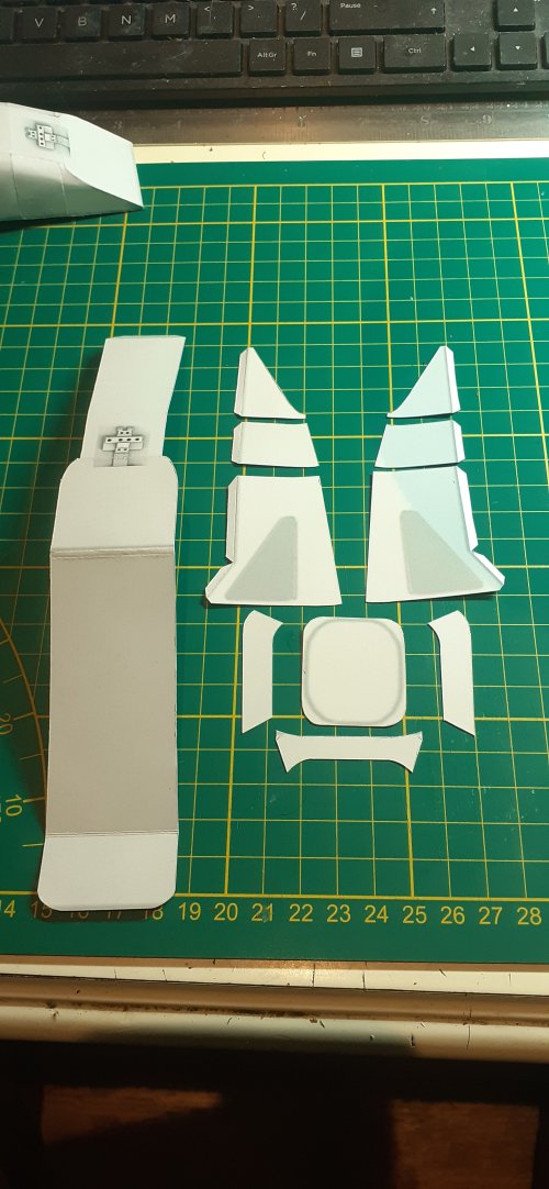
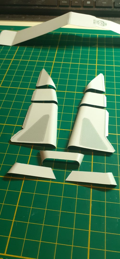
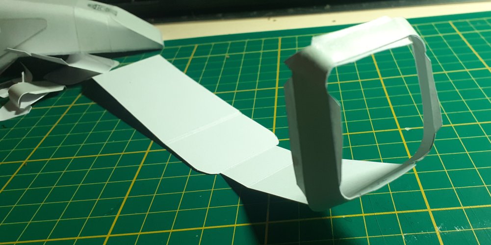
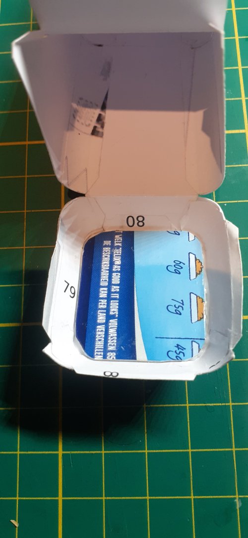
There is nothing difficult here, just follow the instructions. Just make sure everything is square and true when gluing.
The joints between each sub-assembly needs to be as tight as possible, without gaps. I compressed mine together to the limits of structural collapse to achieve this!!
If there is too much spacing between the sub-assemblies, the ends of the rear detail panels will protrude too far over the edge of the lateral spine....

I just had to place the rear hull construction, unglued, onto the lateral spine, just to see what it looks like!!
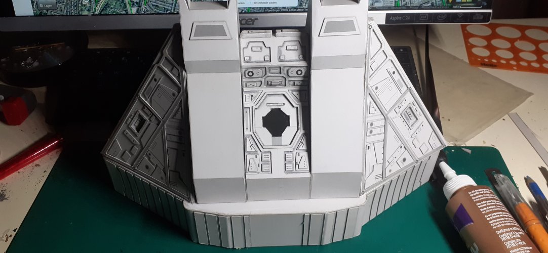
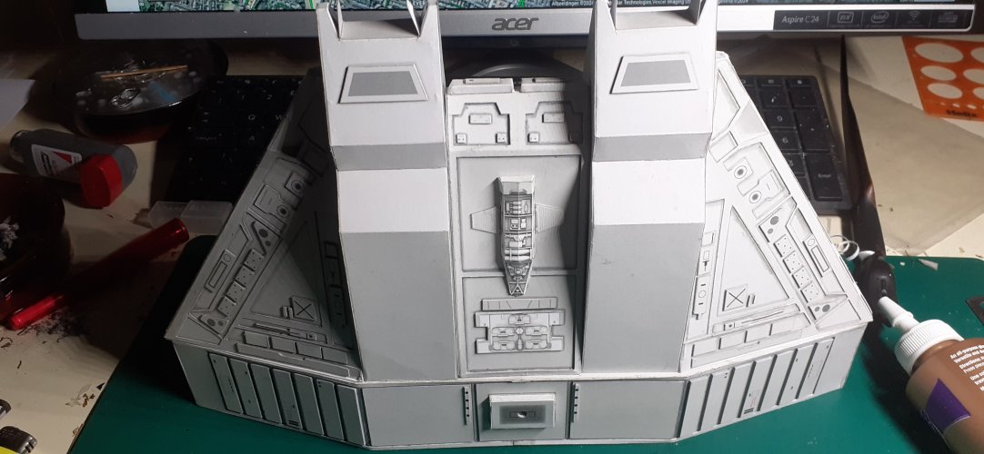
81.jpg82.jpg


And, well, me being me, with good balancing abilities, I had to go one step further........ (The proverbial beer can is 17cm high, btw.)
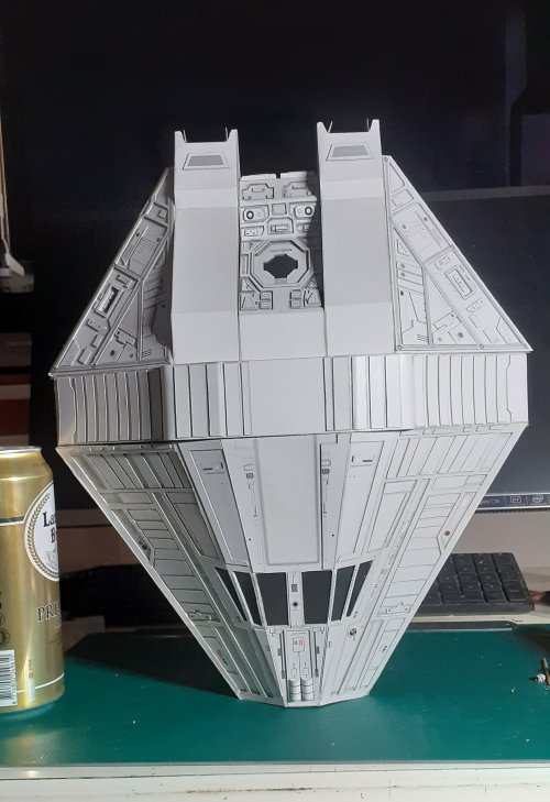
83.jpg


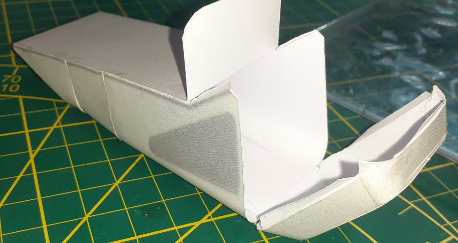
But, then I noticed a few problems like this..... Some parts had pulled away, causing the parts to not join correctly. In this case, the forward hull and the lateral spine.
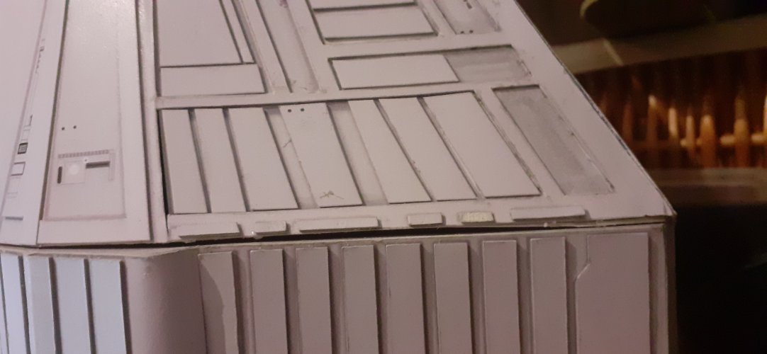
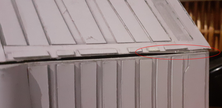
84.jpg
Screenshot from 2025-01-15 18-19-21.png


Time for repairs before I go any further with the build..... :OOPS:

Back soon with more ,when the repairs are done....

:wave:
 
Last edited:
WOW! That is a significant gap.
If I may suggest using a paper putty. I did a tutorial several years ago titled Paper putty, that you might be interested in and help you with dealing with the gap.
Without reading RB's post paper putty is what came to my mind a soon as I saw that! In this case you can call it "space dust" instead of "paper putty". ;)

Yes, that could be done. However, the problem I have here is caused by sections of the sub-assemblies pulling apart.
Hopefully, when these problems are fixed, everything should become true.
We will see.....

My father always taught me: If you need putty to fill gaps, you didn't make it properly in the first place.... Fair comment really. Bless him!
 
Looks like you just have to pull the seams together. That's a great size model, big enough to hold (and let someone handle) without worrying about them breaking it. :)
 
Lets put it all together" ~ The Stylistics


I haven't had a lot of free time the last few days, as I have been helping a friend make their new house livable.
With the few spare hours I've had, I completed the necessary repairs of the fitment issues.

Most of the issues were on the forward hull, where a seam or two had popped loose, or was not sitting true while gluing.
To make sure there were no other protrusions or bumps that would hinder good fitment, I did one final step...

The forward hulls nose and rear panel, and the gluing area of the rear hull, were sanded flat. I did this by tacking a sheet of 600 grit wet-n-dry sandpaper to my cutting mat and using figure 8 movements, sanded the faces flat.
There is no need to go crazy here, the objective is to get all the outer perimeter edges bump and protrusion free. The middle of the panels do not really matter.
As long as all the joints are gap free, job done.
I did not do this on the lateral spine because a lot of texture will be visible after final assembly. I just filed/sanded off any bumps where necessary and coloured it to match the texture.

The hull was then assembled.
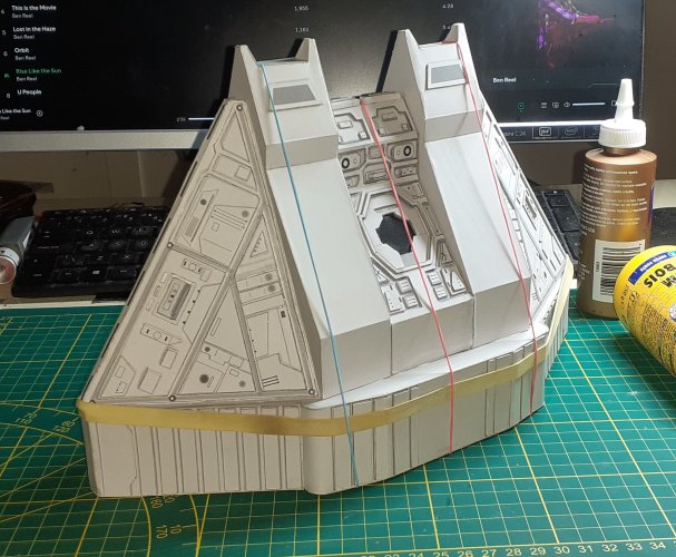
I started by gluing the rear hull to the lateral spine, making sure the spine is the correct way around. Use the block on the bottom of the lateral spine as reference. The block is offset towards the rear edge of the lateral spine. Various combinations of elastic bands were used to hold it all together while drying.

86.jpg87.jpg


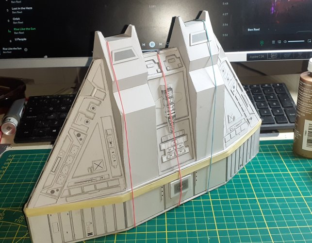
And the same procedure for the forward hull....

89.jpg88.jpg


I left everything to dry thoroughly for a couple of hours. In this time I bashed together a temporary stand to test the mounting system.
The nose of the ship was then glued into position.
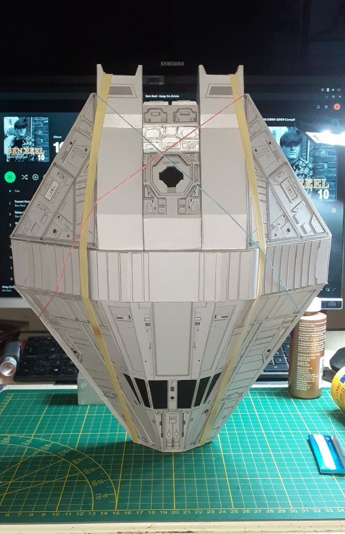
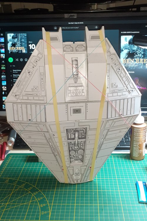
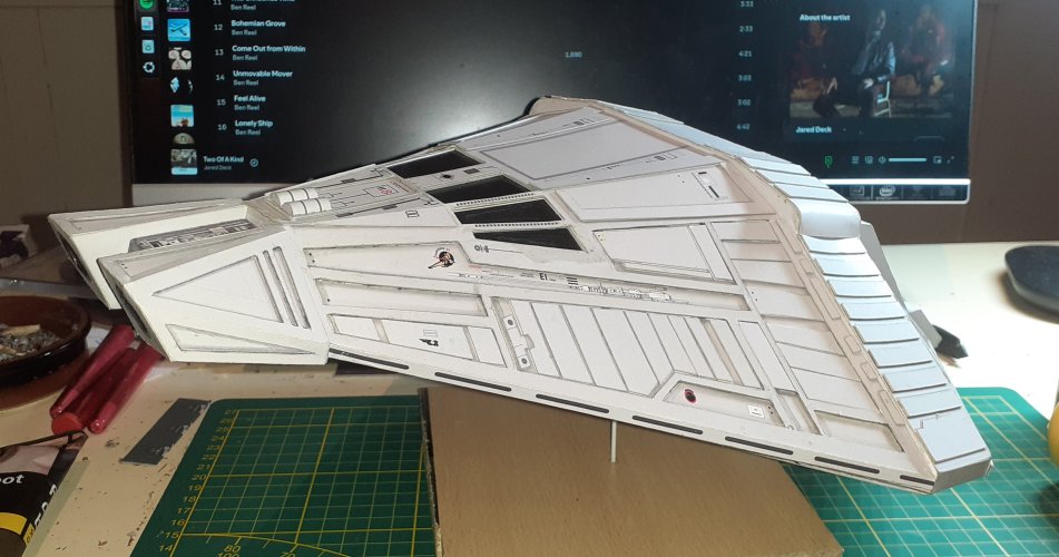
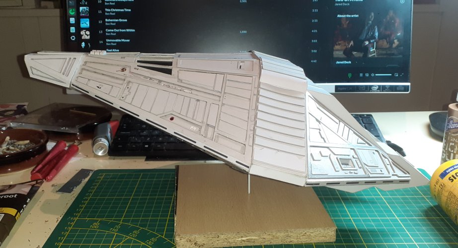
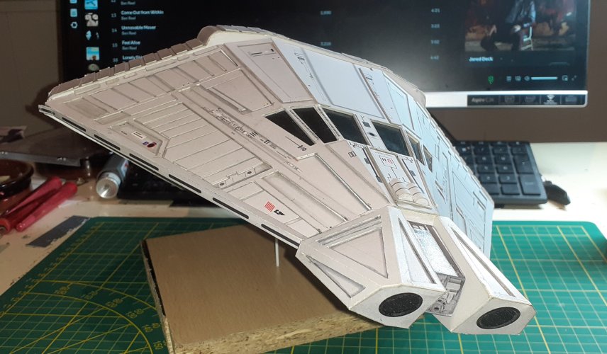
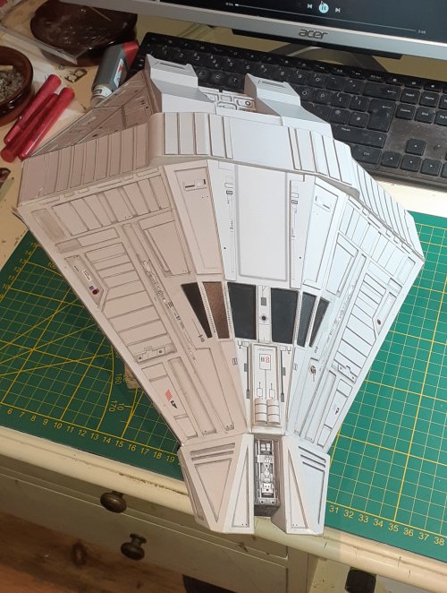
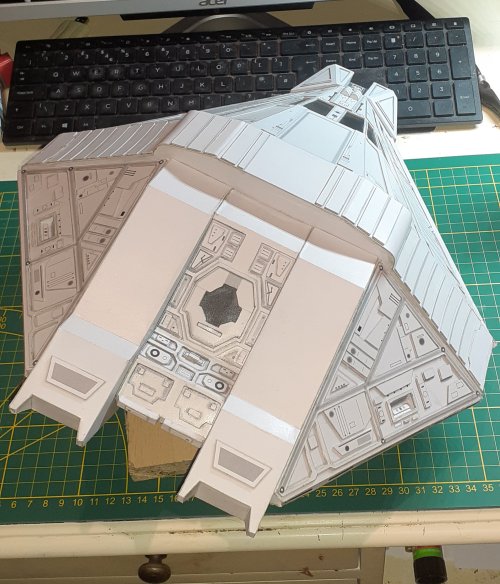
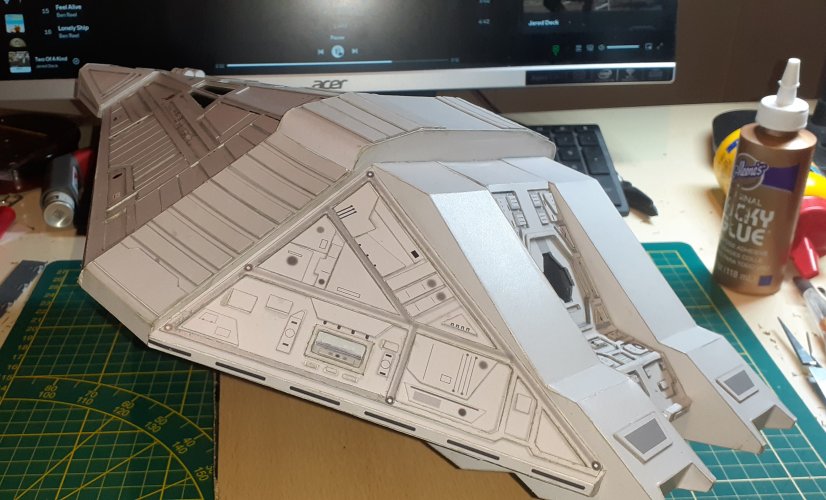
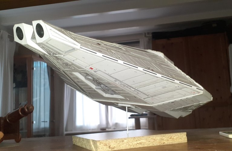
And I can't believe I'm saying this, but the main hull construction is complete!!!!
I've been waiting a while for this moment!

So, here's the pics!

90.jpg

91.jpg
94.jpg95.jpg93.jpg
92.jpg96.jpg


I'm pleased with that!

Next instalment, the parts I have been dreading...... The engines.......!

See you soon!

:wave:
 
Last edited:
Oh man, that is awesome. I really like that bottom pic. I'm at a loss for words. :)
 
  • Like
Reactions: DanBKing
"There is no exit from the circle of one's beliefs." ~ Keith Lehrer

As promised, and dreaded, the beginning of the engines..

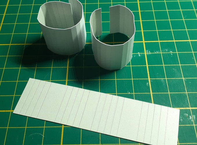
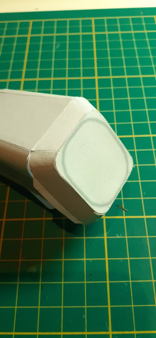
The not so circular exits were made up first.

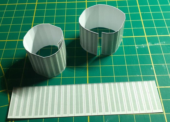
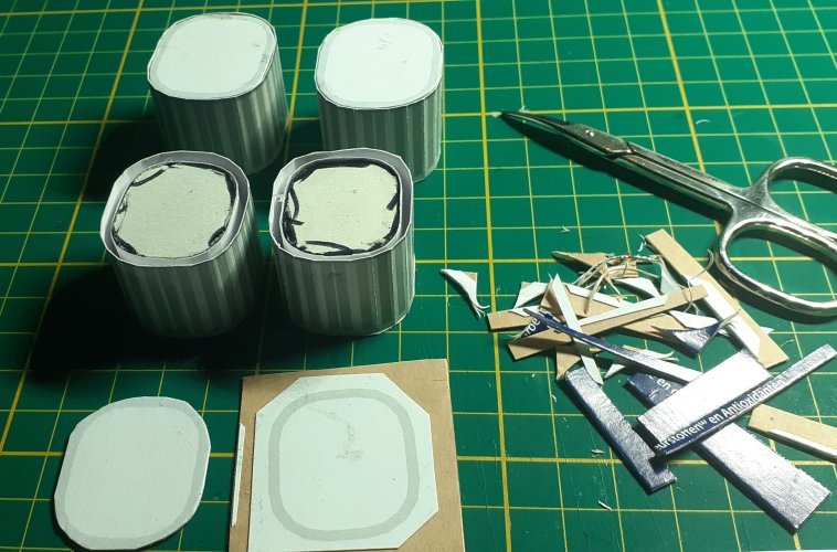
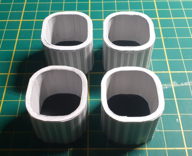
The inner and outer skins were scribed, folded to shape and glued......

97.jpg98.jpg


I forgot to take detailed pics of the next step, but I hope I can explain it well enough, with reference to the pics below...

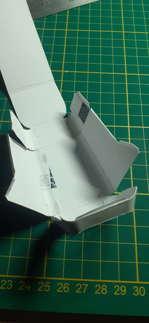
Part 329, the rear end of the nozzle, was cut roughly from the parts sheet, leaving as much white space around it as possible.
The centre of the part was then cut out. The extra white space helped keep the thin part in shape.
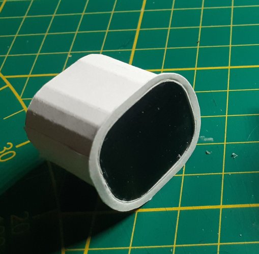
I then laminated part 330, the inner nozzle cap, to 1mm card. After lots of trimming and fit checking, part 330 fit like a 'bug snug in a rug' inside the inner nozzle skin. Using this as a form, I pushed it to the front of the nozzle, without glue. This helped in coercing/forcing the inner skin into shape while gluing it to part 329.
Once the glue had dried, I cut away all the extra white space around part 329.

99a.jpg

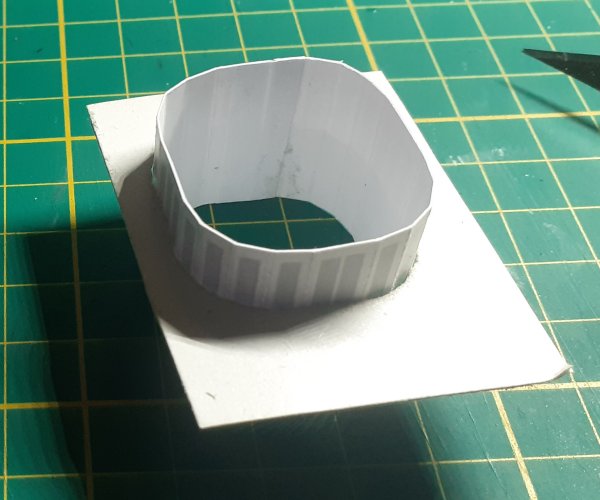
I performed a similar operation for the outer skin. I made up an outer template to coerce/force the outer skin to shape while gluing to the previous assembly.

99b.jpg

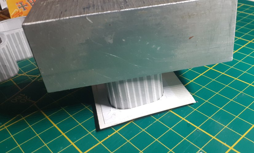
With the inner and the outer skin formers still temporarily in place, both parts were glued together and weighted down to dry.
Thereafter, the outer former was removed, the inner former/part was pushed to the back of the inner skin and glued into place.

100.jpg


Because the inner skin is about 1.5mm shorter in length than the outer skin, I decided to pack out the space between with laminations of card to fit.
By doing this, I had a much greater gluing area when attaching them so the engines later. Better than just edge gluing the outer skins to the engines.

101.jpg


So, the nozzles are done.
Not my best work, but you get the idea......

102.jpg


I put the nozzles aside and started the prep work for the engines.

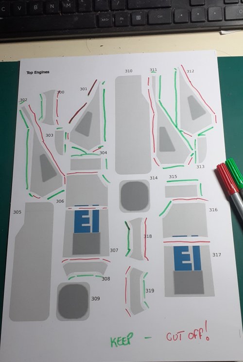
The designer, quite rightly, suggested using back tabbing when assembling the engines.
With this in mind I marked out the engine parts on the template.
Green, the tab stays with the part.
Red, the tab is removed.
I then printed the engine parts pages onto copy paper, which will be used for creating the back tabbing parts.
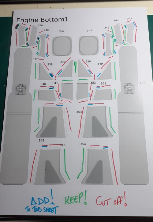
Basically, you do the complete opposite when cutting the tab parts out than above... Green, remove and red, keep.

103.jpg

However, the lower engines required tabs to be added to the tabs page... As shown in blue below...

104.jpg


I started at the bottom....
All the engine parts were back tabbed and then shaped before assembly.

105.jpg106.jpg


I started assembly with the front of the lower engines.

107.jpg

Followed by each side panel in turn.
I've said this before, many times, accuracy of fitting here is paramount!

108.jpg

I capped off the end of the engine and added a strengthening piece behind.

110.jpg111.jpg

The rest of the engine construction was completed, except for the attachment of the front section. You'll see why later.
Sorry for the bad pic....

109.jpg

See you soon(er)

:wave:
 
Lets put it all together" ~ The Stylistics


I haven't had a lot of free time the last few days, as I have been helping a friend make their new house livable.
With the few spare hours I've had, I completed the necessary repairs of the fitment issues.

Most of the issues were on the forward hull, where a seam or two had popped loose, or was not sitting true while gluing.
To make sure there were no other protrusions or bumps that would hinder good fitment, I did one final step...

The forward hulls nose and rear panel, and the gluing area of the rear hull, were sanded flat. I did this by tacking a sheet of 600 grit wet-n-dry sandpaper to my cutting mat and using figure 8 movements, sanded the faces flat.
There is no need to go crazy here, the objective is to get all the outer perimeter edges bump and protrusion free. The middle of the panels do not really matter.
As long as all the joints are gap free, job done.
I did not do this on the lateral spine because a lot of texture will be visible after final assembly. I just filed/sanded off any bumps where necessary and coloured it to match the texture.

The hull was then assembled.
I started by gluing the rear hull to the lateral spine, making sure the spine is the correct way around. Use the block on the bottom of the lateral spine as reference. The block is offset towards the rear edge of the lateral spine. Various combinations of elastic bands were used to hold it all together while drying.

View attachment 223094View attachment 223093


And the same procedure for the forward hull....

View attachment 223090View attachment 223091


I left everything to dry thoroughly for a couple of hours. In this time I bashed together a temporary stand to test the mounting system.
The nose of the ship was then glued into position.
And I can't believe I'm saying this, but the main hull construction is complete!!!!
I've been waiting a while for this moment!

So, here's the pics!

View attachment 223092

View attachment 223089
View attachment 223086View attachment 223085View attachment 223087
View attachment 223088View attachment 223084


I'm pleased with that!

Next instalment, the parts I have been dreading...... The engines.......!

See you soon!

:wave:
Just a huge WOW!!
 
  • Like
Reactions: DanBKing
That are going to be some great looking engines. Nice to read how you add some ectra parts.