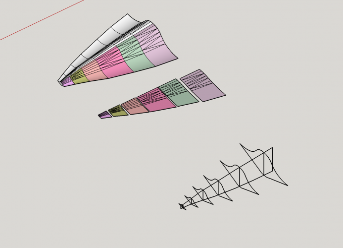
Sr-71B 1:45 build thread

One more thing: Your physical model looks great so far. You may choose to rebuild it in SketchUp. Scan the skeleton cross-sections, trace them in SketchUp, align them like they are in reality and combine them with lines. This will give you the fitting shapes you are looking for. ;)
 
  • Like
Reactions: micahrogers
First the model is cleaned up, then you use the Flattery plugin to unfold it in SketchUp. Then you export the unfold to *.svg and edit it in Corel or InkScape.

You need Pepakura only if you want to export bitmap textures.
 
  • Like
Reactions: mijob
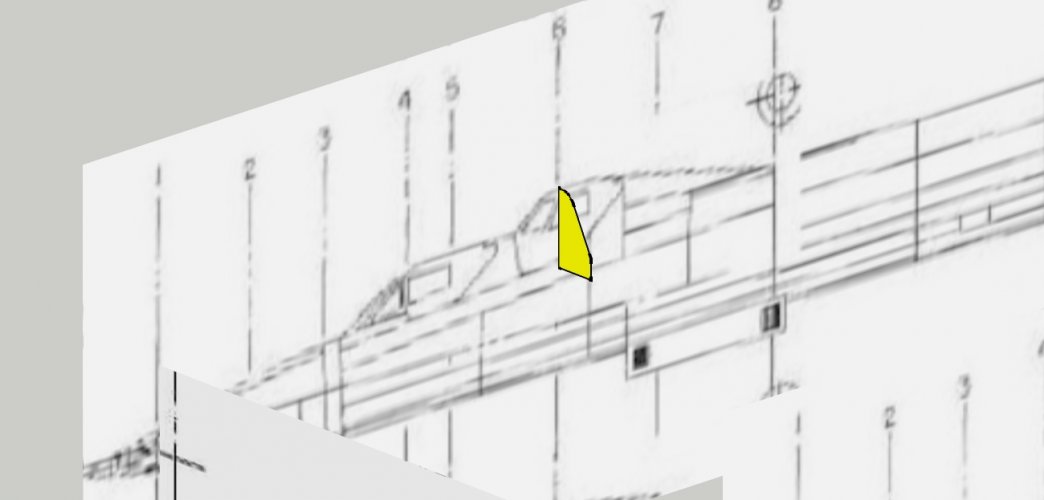
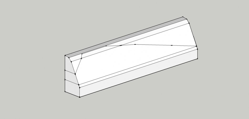
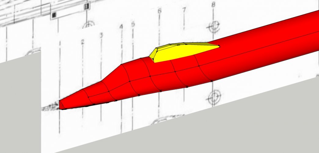
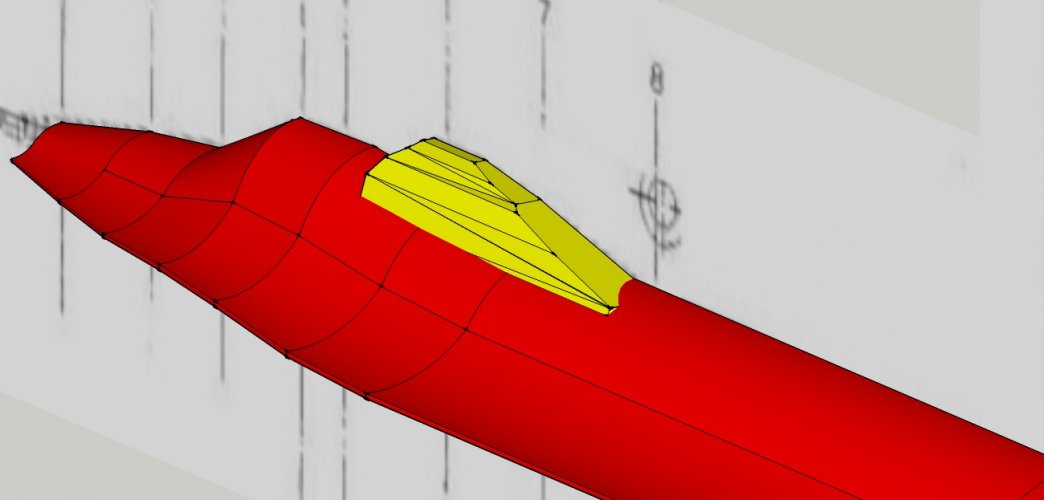
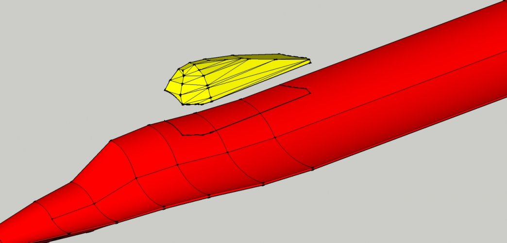
Sometimes it is advisable to create new objects to make working on the mesh easier. In this case I would model the second cockpit as a separate piece. To match the shapes of the blueprint you can proceed according to what I showed you above. However, if you are stuck and do not know exactly how to tackle a shape you may proceed like a woodcarver or stonemason. You create a block which follows the front view:

21.jpg

22.jpg

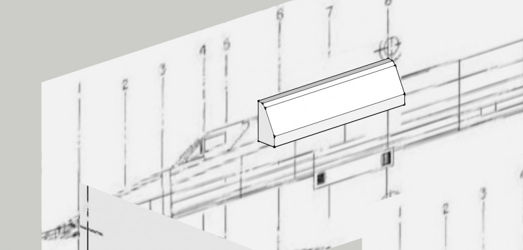
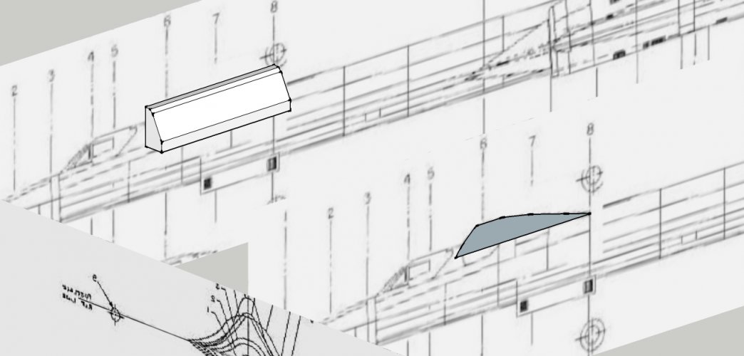
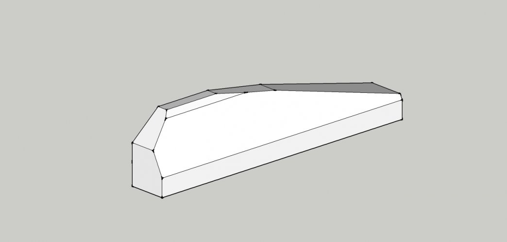
Then you trace the shape of the side view:

23.jpg

and pull it out so that it penetrates the first block:

24.jpg

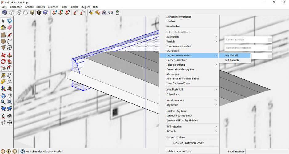
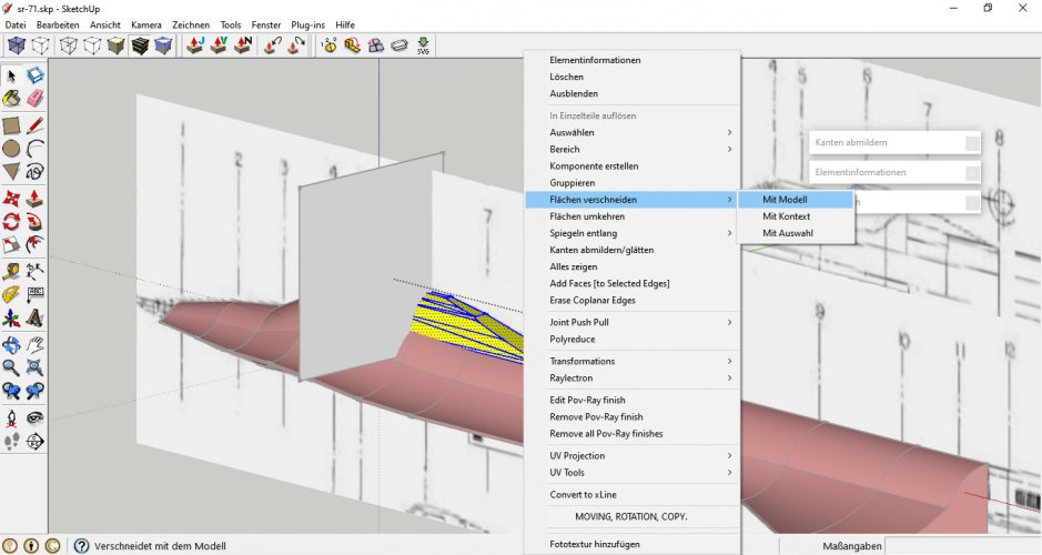
Select the whole block > right-click > intersect faces with model:

25.jpg

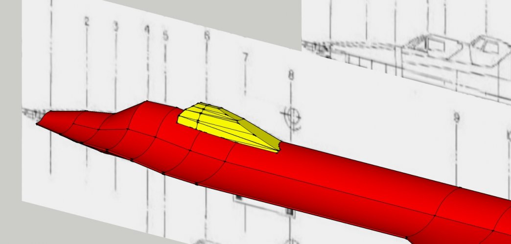
This creates a cut which follows the second block from the side.

26.jpg

27.jpg

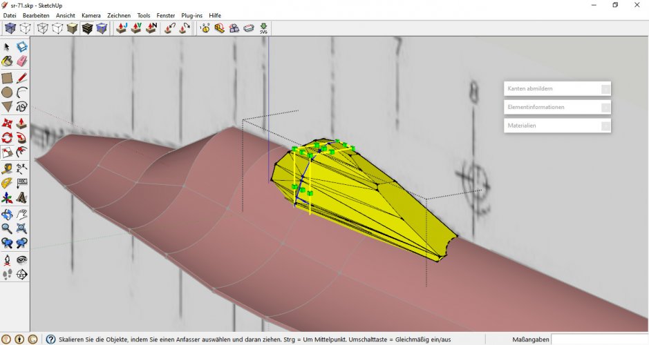
Delete everything around it which is not needed:

28.jpg

29.jpg

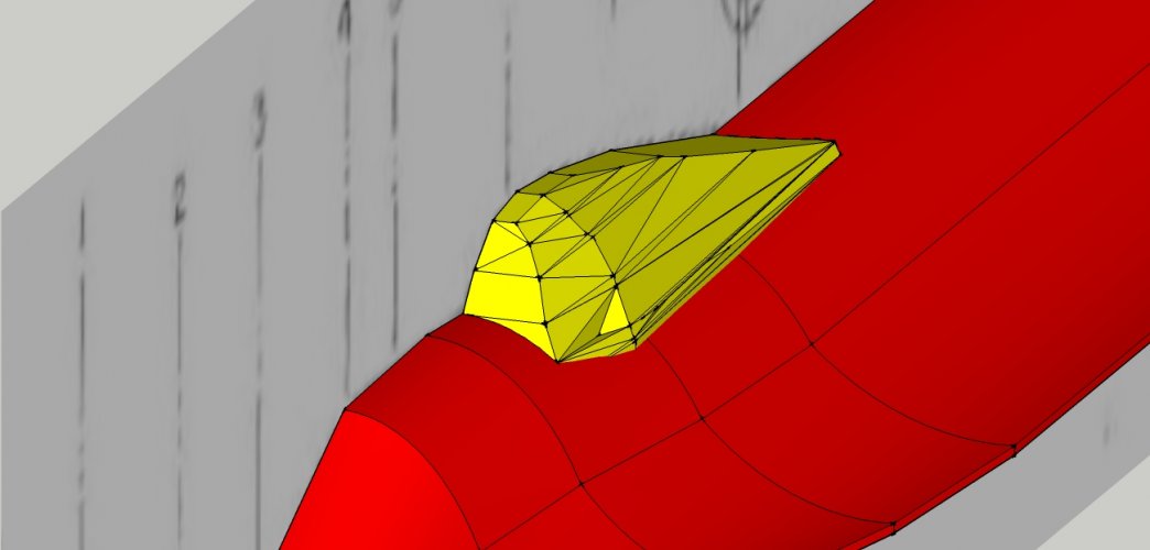
First test view:

30.jpg

Not too bad. If you want to refine the shape draw additional lines onto the faces and move them on either axis to create a smooth curvature:

31.jpg

32.jpg

You may even add a new division area by creating a simple rectangle, grouping it and moving it to the desired position:

33.jpg

34.jpg

Select the shape which is to be refined and intersect with model:

35.jpg

36.jpg

Remove the rectangle and continue manipulating the object.

37.jpg

38.jpg

This will create additional lines and maybe distortions. You have to keep in mind that every face (= every triagle you see) will become a shape which you will have to cut out, fold and assemble. Too small faces will become very tricky to work with and may make the build frustrating later. To avoid that reduce the number of faces and combine lines which are very close together. I do that manually because that gives you the best results and control over the shape.

39.jpg

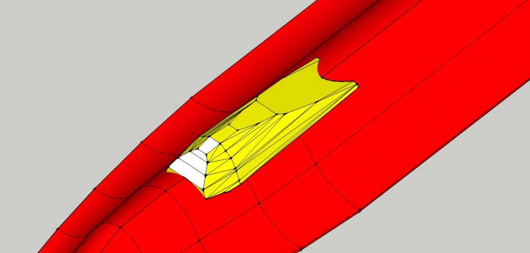
This view of the cockpit shows you the final cockpit. You may unfold the part already but it would not fit on the fuselage because there is superflous material which has to be removed first.
 
Again use the intersect with model function to "print" the shape of the fuselage onto the cockpit:

39.jpg

Remove the areas in question:

40.jpg

41.jpg

With fuselage in place:

42.jpg

You can see that the bottom of the cokcpit follows the shape of the fuselage nicely. You will not have any trouble with assembly now.

To create a position marker which makes it easier to place the cockpit you may intersect the fuselage with the cockpit, too. The resulting area can be cut out completely or you can leave it and unfold it.

43.jpg

If you are content duplicate the shapes, mirror them and align them to make one complete plane:

44.jpg

45.jpg

Ungroup the fuselage halves and form a new group of the fuselage. Remove unnecessary lines which may appear between the halves. Especially on models with straight faces you can eliminate all lines which are in the middle to form one complete face.

46.jpg
 
Now comes the fun part: The skeleton!

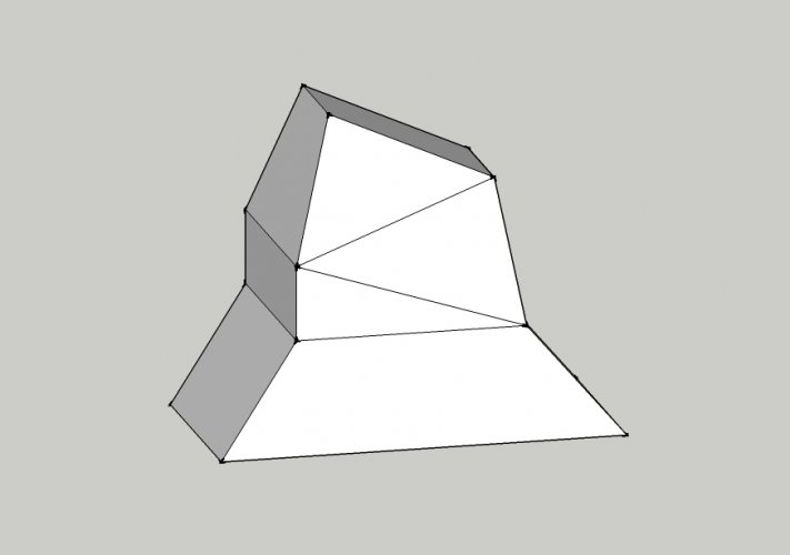
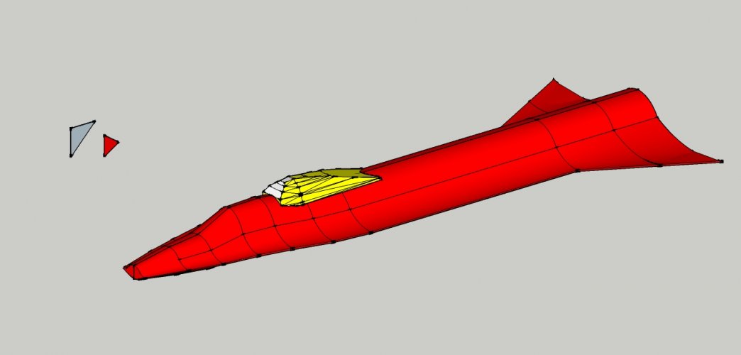
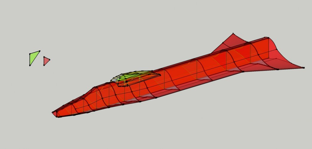
Simplify the model until only the outer hull is left. Everything inside must go, especially remnants of former ortho slices. Sometimes additional faces are created inside the hull when you are dealing with simple geometric shapes or faces which are parallel, like faces of box-like structures with few or no curves like this one:

51.jpg

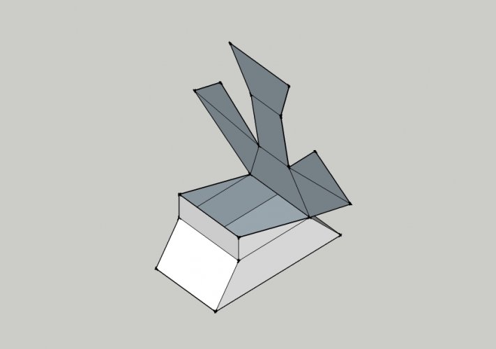
Those faces are invisble at first but become visible during unfolding:

49.jpg

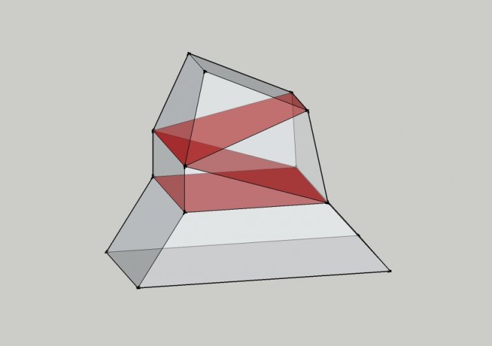
or when you switch to the half-tansparent view:

52.jpg

They are not needed and must go:

50.jpg

Sometimes you see "garbage faces" in Pepakura models which have been moved out of the print area. Those "garbage" is what happens if the model is not properly cleaned up. This is no big thing though, the model will assemble fine, but it is better to get rid of it in order not to confuse the builder. ;)

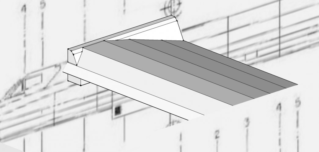
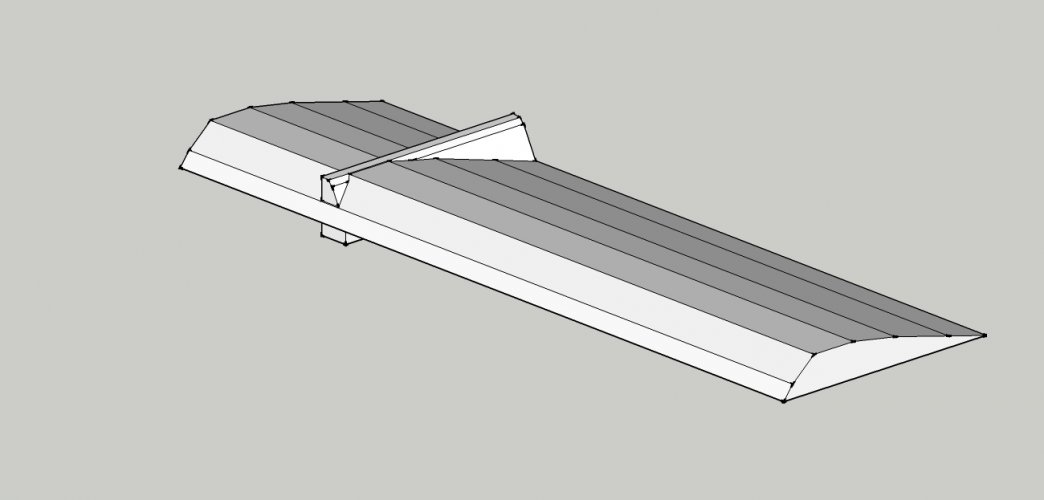
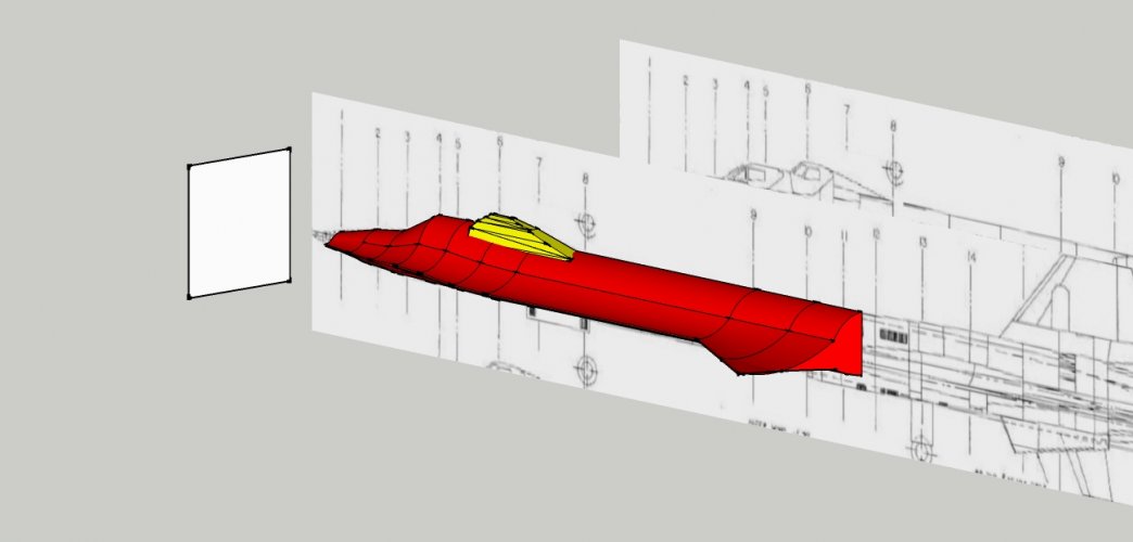
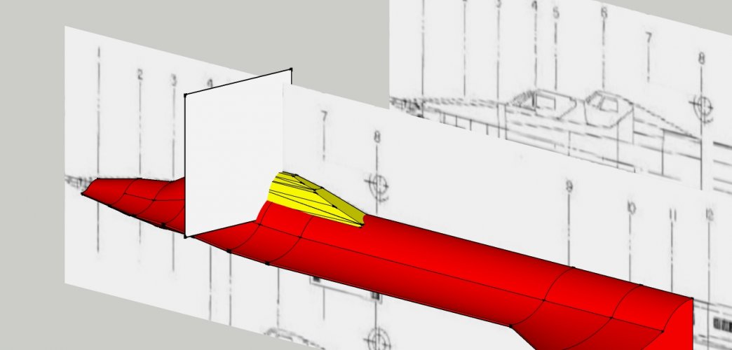
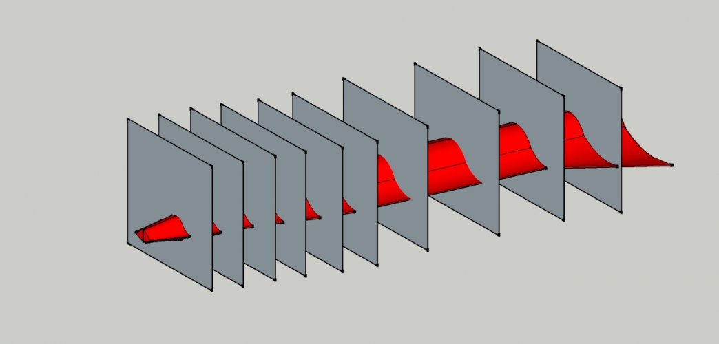
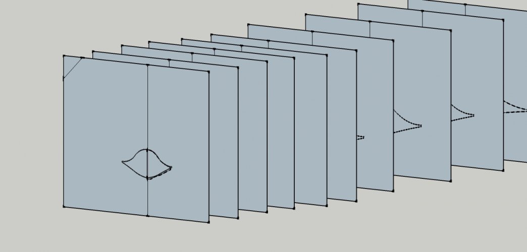
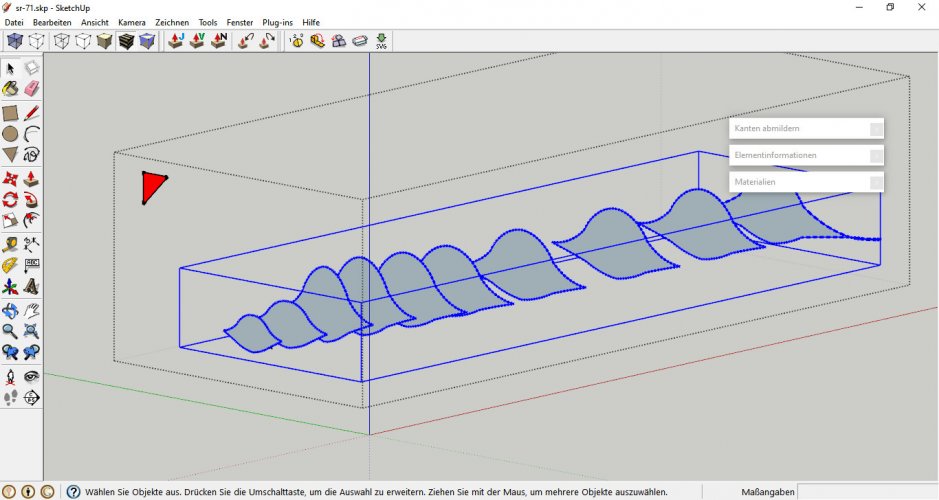
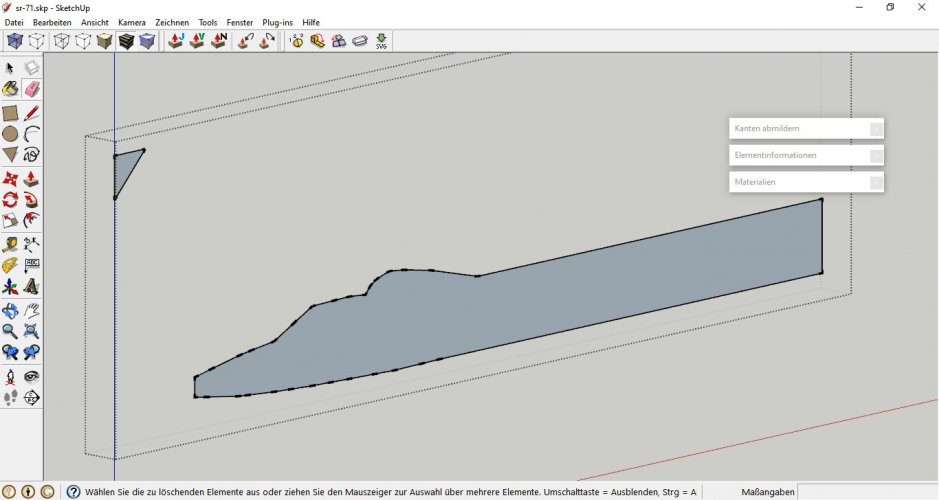
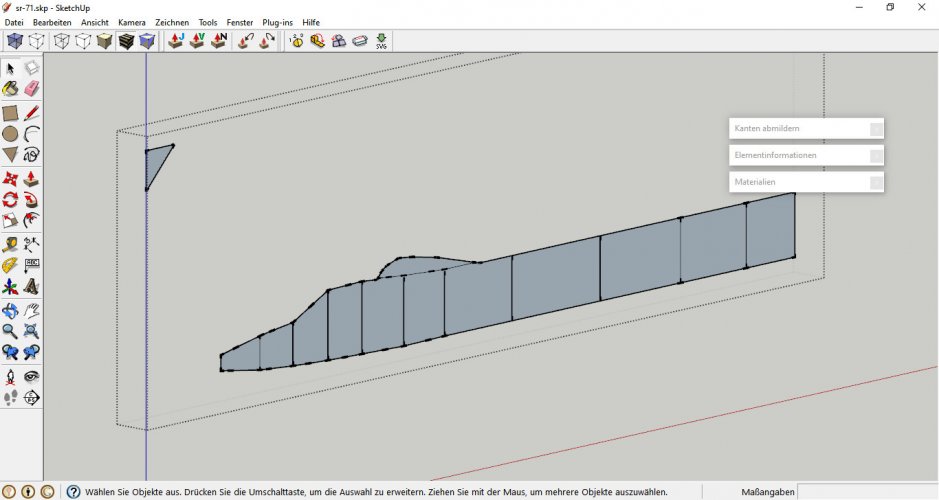
So with a completely hollow model you are free to determine the shape of the skeleton. If you have a blueprint with cross-sections you may use that as a guide. Create a series of rectangles, group them, move them to strategic points and intersect them with the model:

53.jpg

54.jpg

55.jpg

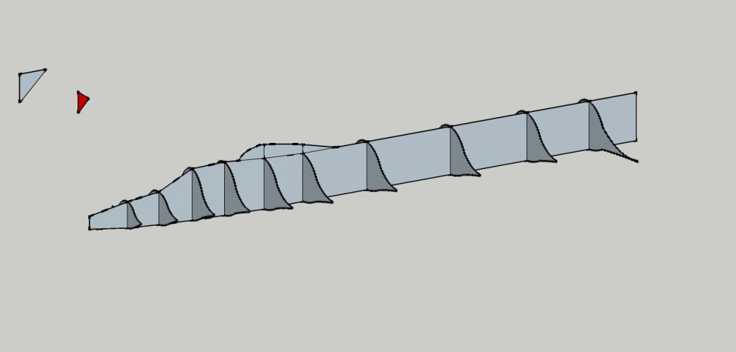
To see where the "ribs" are places intersect the "spine" with the ribs:

56.jpg

Important: Now draw a simple shape on one of the skeleton groups. This will help you with selecting the parts later because they are going to vanish inside the model:

57.jpg

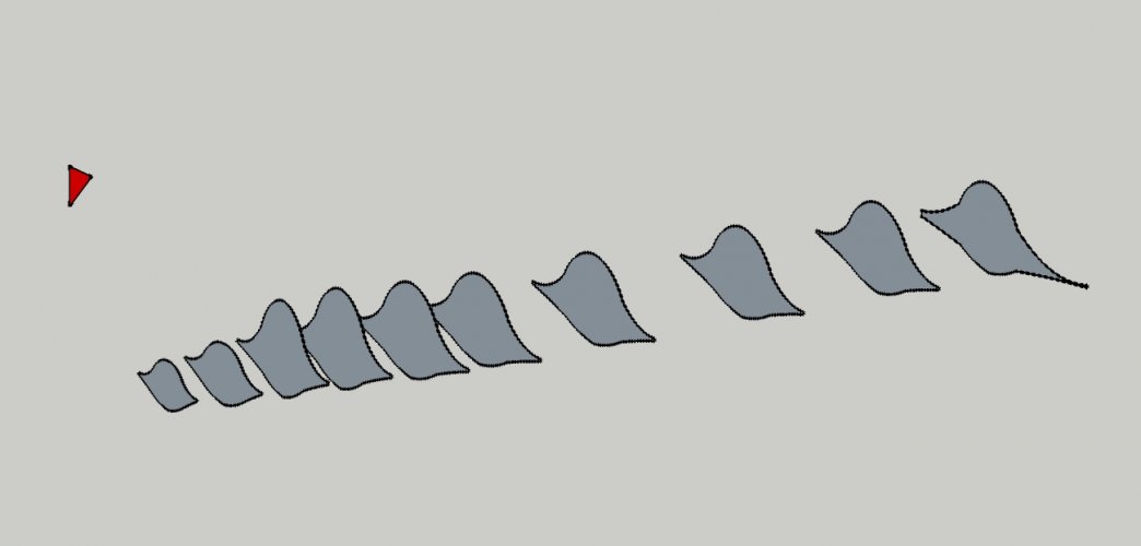
Remove all unnecessary lines to create clean skeleton parts:

58.jpg

59.jpg

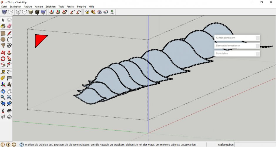
The little triangle in the top left corner is part of the respective group. Once you make the hull visible again it will become a bit tricky to select the skeleton, especially after offsetting:

60.jpg

To select a skeleton group just double-click on its respective triangle.
 
Last edited:
Now comes the fun part: The skeleton!

Simplify the model until only the outer hull is left. Everything inbetween must go, especially remnants of former ortho slices. Sometimes additional faces are created inside the hull when you are dealing with simple geometric shapes or faces which are parallel, like faces of box-like structures with few or no curves like this one:

View attachment 218505

Those faces are invisble at first but become visible during unfolding:

View attachment 218503

or when you switch to the half-tansparent view:

View attachment 218506

They are not needed and must go:

View attachment 218504

Sometimes you see "garbage faces" in Pepakura models which have been moved out of the print area. Those "garbage" is what happens if the model is not properly cleaned up. This is no big thing though, the model will assemble fine, but it is better to get rid of it in order not to confuse the builder. ;)

So with a completely hollow model you are free to determine the shape of the skeleton. If you have a blueprint with cross-sections you may use that as a guide. Create a series of rectangles, group them, move them to strategic points and intersect them with the model:

View attachment 218507

View attachment 218508

View attachment 218509

To see where the "ribs" are places intersect the "spine" with the ribs:

View attachment 218510

Important: Now draw a simple shape on one of the skeleton groups. This will help you with selecting the parts later because they are going to vanish inside the model:

View attachment 218511

Remove all unnecessary lines to create clean skeleton parts:

View attachment 218512

View attachment 218513

The little triangle in the top left corner is part of the respective group. Once you make the hull visible again it will become a bit tricky to select the skeleton, especially after offsetting:

View attachment 218514

To select a skeleton group just double-click on its respective triangle.
I can NOT THINK OF THE APPROPRIATE WORDS!!!!! This is an absolute college course in sketchup, 3d modeling, design thinking, and paper craft. Thank you sir. I will have to give you a gift at some point. I will NOT forget your kindness
I am writing notes from this thank you SO MUCH!!!
 
I really hope this helps! :)

As I said, this is like a crash course in SU with a simple example which is in no way accurate to the real thing (if I would model the real thing I would need a few weeks to get it done correctly ;) ).

Now things become tricky. It is time to determine the scale of the model. Rescale everything accordingly and save it as a new model. Do not delete the original working file. Add the scale to the file name so that it becomes easily identifiable.
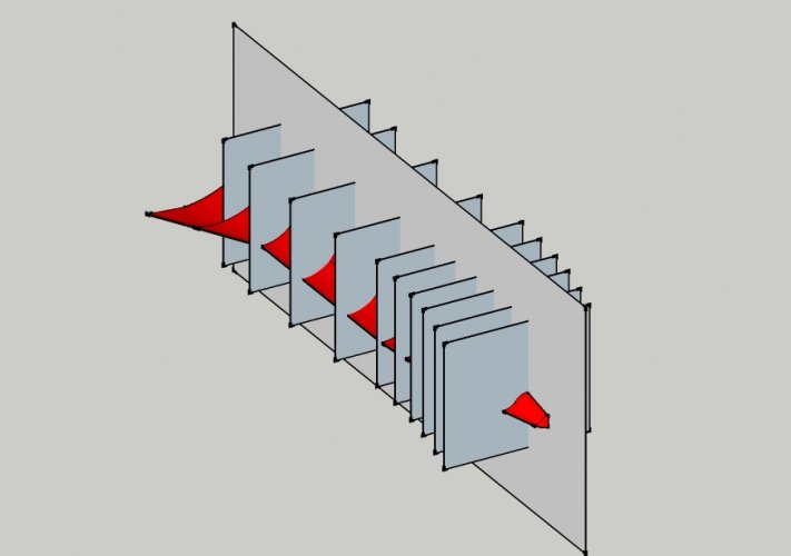
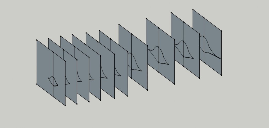
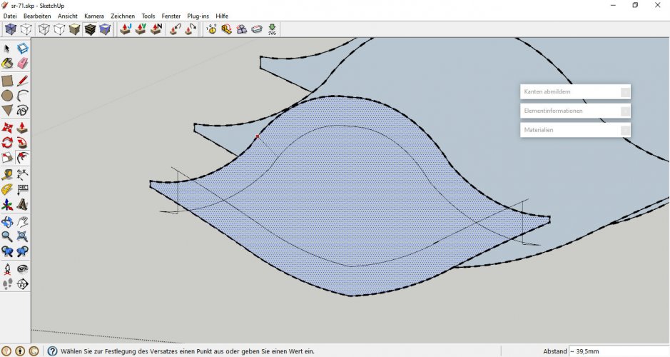
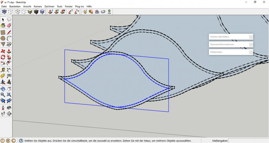
Now select the skeleton group and offset each (!) part by 0.2 - 0.3mm. That way you compensate the parts for the paper thickness. If you do not do that the skeleton will be as big as the hull and you will never be able to insert it correctly. If you attempt that the hull will bulge and crease and the skeleton might eventually be squished and become useless.
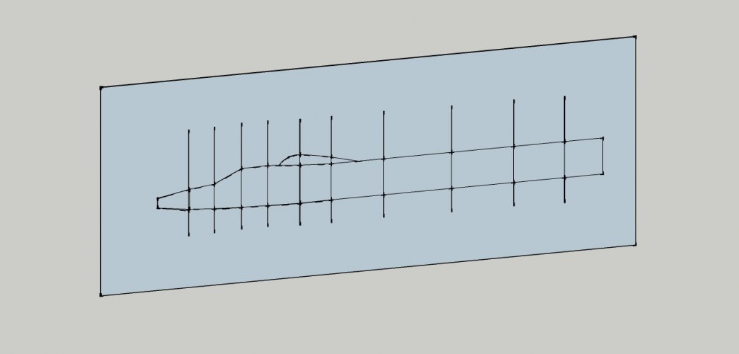
SketchUp comes with a handy offset tool which does the job just fine. Of course you may do that after unfolding in a graphic program with an offset feature, too.

61.jpg

62.jpg

Now clean up the skeleton pieces and delete all unnecessary lines:

Double-click the center of each rib and group it:

63.jpg

Proceed with the others. Select all of them and group them:

64.jpg

65.jpg

Select the outlines of the previous ribs and delete them so that you end up with the offsetted ribs only.

Select the spine. Delete all lines inside to get a clean face:

66.jpg

Offset the face to compensate for the paper thickness like above, remove the bigger outline and intersect the spine with the model again to create placement markings for the ribs:

67.jpg

And with this operation preparing the skeleton is finally done! :)

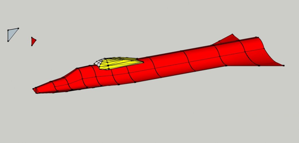
And now watch what happens when you deselect the group:

68.jpg

The skeleton is covered up by the model completely! There is no way you can access it again easily - aside from those little triangles in the top left corner. Of course you may achieve the same effect by creating a scene which enables you to toggle elements on and off but I found this solution easier. ;)
 
Last edited:
Fantastic start! My first attempt was the Landram. It was nowhere near as sophisticated as the Blackbird! :)

Make good use of grouping key elements. If a section is too complicated start with a rough shape like a simple block, subdivide the lines or add lines and shape the block to whatever it is supposed to be. Julius Perdana's models are great examples of complex designs made using simple shapes. I recommend studying especially his Iron Man model. It gave me the idea to make the final version of the Landram "horns".
 
Last edited:
Useful links:


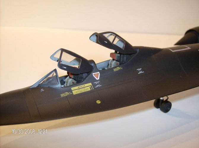
That double cockpit will be a challenge. I'd study this model, and make the fuselage section first. I would try and fit the cover afterward. Some of us use water, making molds out of two part epoxy, to get the shape, use that as a plug to put wet paper over. This allows you to get compound curves, and when it dries, you have the shape you want. ;)

SR71.jpg
 
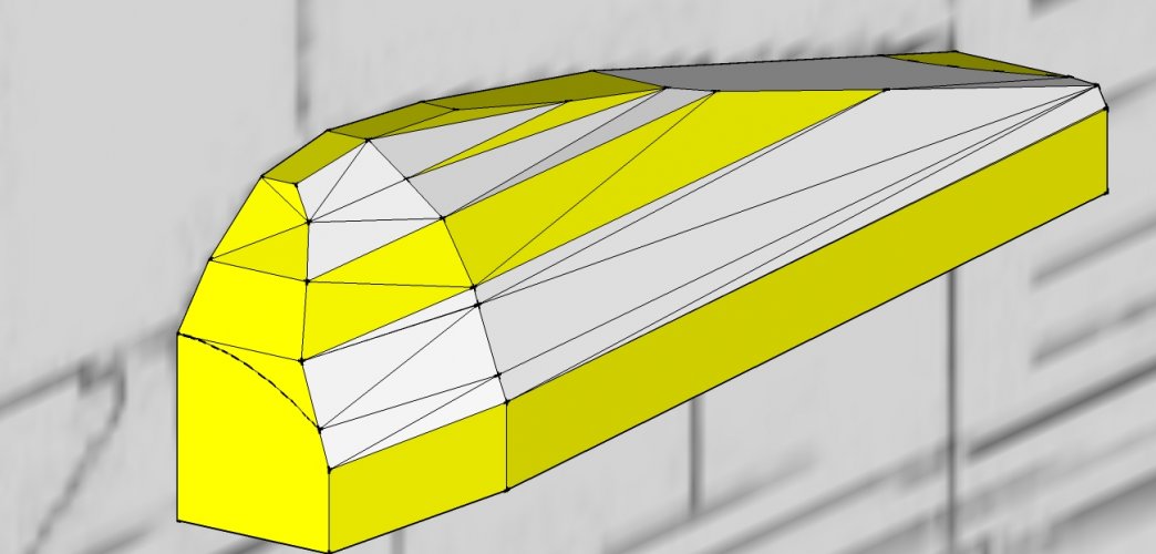
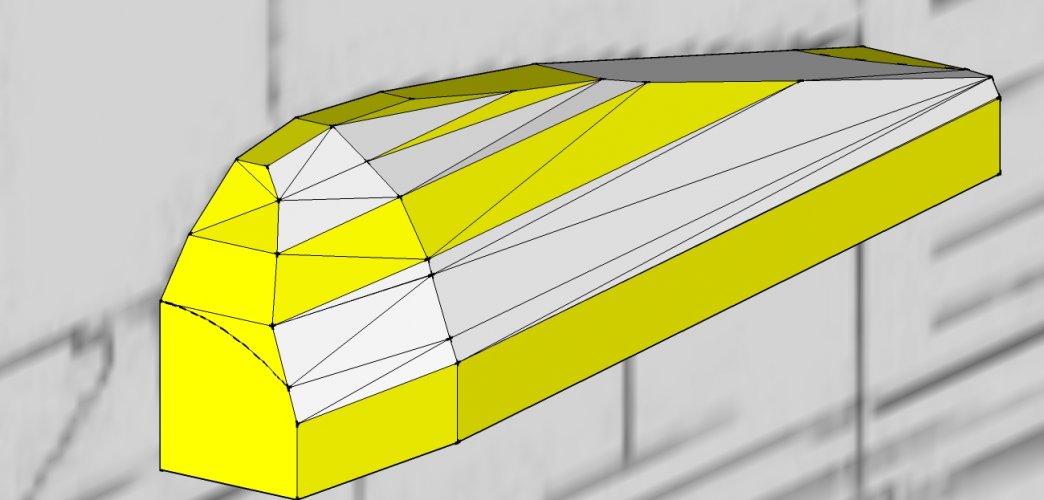
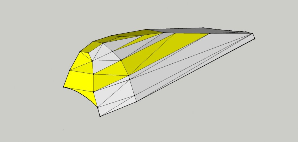
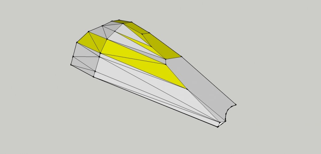
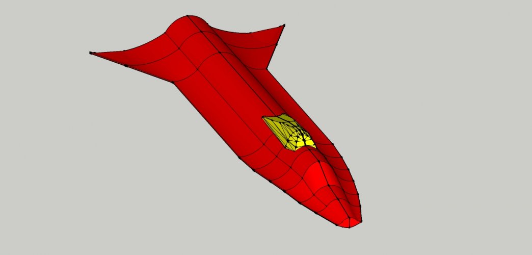
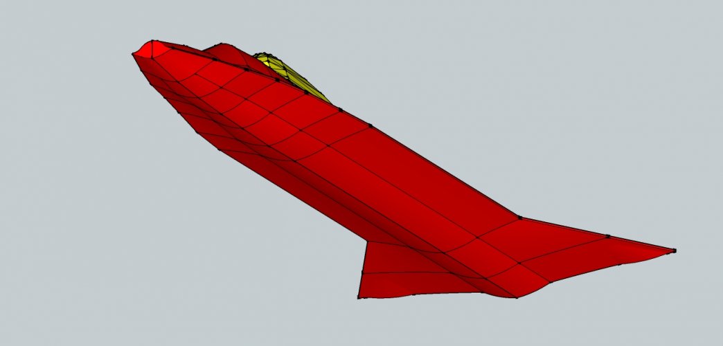
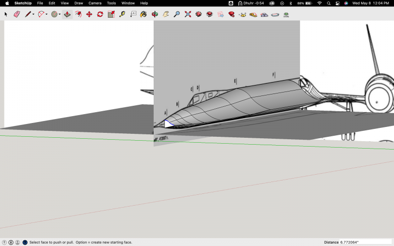
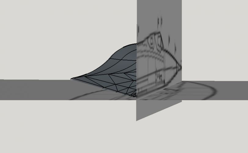
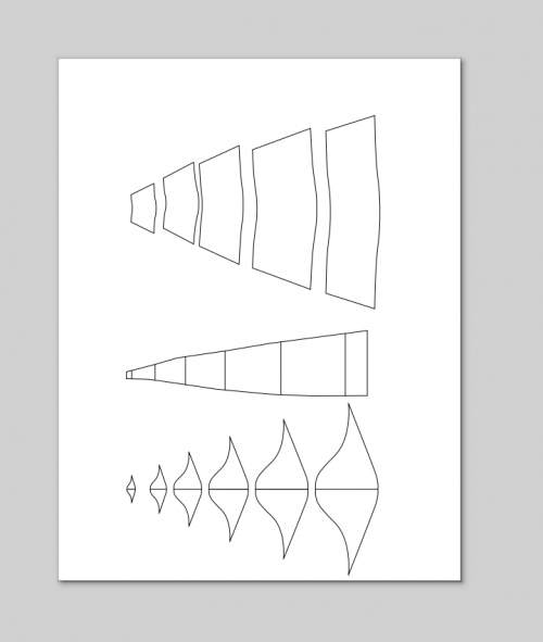
I got So exited that I just built a quick nose section using RF'S teachings and I have my FIRST PRINTABLE!!!!! My building techneques are questionable at best but I'm learning every minute!!!!! I used flattery

but flattery has an issue with unfolding the many triangle facets which make up the surface. So I used a plugin called "unwrap and flatten"and exported it using flattery To inkscape and now I'll put together a small part tomorrow I hope!

Oh also when I intersect the skeleton it always becomes an open face and loses color and just becomes lines....So until I figure it out I just screen shot it and scaled it in inkscape.....
Screen Shot 2024-05-08 at 7.00.56 PM.pngScreen Shot 2024-05-08 at 7.01.03 PM.png