

TRANSPORT CENTRAL 1974-2018
The idea for a large multi-mode transit center was born long, long ago; and, in a place far, far away (actually around 1974). In the late 50’s-60s HO scale buildings were quite frankly dinky and the biggest around were the Revell Bakery, Print shop and Engine House (all basically the same building) in plastic and some Suydam items in thick cardstock. I wanted a very large building to handle trains, streetcars and buses. TRANSPORT CENTRAL was an obvious choice for the name. Starting in 1975 many sets of ‘full size’ drawings were made as my ideas rapidly changed. It’s always pie in the sky for me at first and I envisioned a fully detailed and lighted building with large brass rectangular shapes at each corner with telescoping smaller shapes so each floor could be raised up and locked in place to view the inside. And, as usual, I quickly realized I’d never do this too elaborate idea and so scaled back the plans several times.
1975:
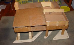
I wanted something modern and up to date that would not look 1900-1930 as many model railroaders liked for their era of operation at that time. Finally certain features looked more and more attractive and some scale floor plans were made. The design was strictly freelance on what I thought would look good and there is no particular building anywhere I was using as the basic model. Eventually a full size cardboard mock-up was made.

PHOTO 1 above: Showing its age, the cardboard mockup still exists after years of storage in an attic or basement. It’s leaning to the right, weakened by moisture absorption. The model as built so far doesn’t nearly match the mockup as reality often differs from dreams. But, this is where TRANSPORT CENTRAL started.
1993:
In the mid-90s I acquired about 20 Kibri plastic “brick” sheets at a good price (approximately 5” x 7” in size) from a dealer who couldn’t sell them. These sheets looked good; but, had one problem in that they varied in thickness being almost 1/8” thick at one end tapering down to around 1/16” at the other end. However, at this point I was gung-ho again and I transferred the dimensions from my drawings to the backside of the Kibri brick sheets; some dimensions had to be altered slightly to accommodate the size of these Kibri sheets. Then I laboriously carved all the fancy widow openings with an Xacto knife (53 of them). Many of the windows were purposefully large ‘picture window types’ to allow a view of what was meant later to be a super-detailed interior with lights. Carving through that thickness of material took forever, and made my fingers sore. Also I had to use a file to smooth out the irregularities in the openings. I glued the sheets together to form the building shell which had dimensions of 15-3/4” wide, 12-7/8” deep (long dimension including the overhang at the front right) and 4-7/16” tall (3 floors). I epoxied Plastruct tubing as vertical and horizontal wall braces to make the building more rigid and to eventually hold the 2nd, 3rd floors and the roof. The horizontal braces for the 2nd floor were wider than those for the 3rd floor to allow the “floors” to be easily dropped in place and to be removed if needed for interior work at later times. The bottom floor was made from Evergreen 1/8” scribed squares sheet (giant size sheet) sprayed light gray.

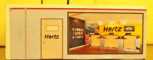
Photo 2a above: The empty shell was packed away for years as the real world intruded again as in making a living, raising a family, and a 1000 other things. What little modeling I did was strictly ready to run during this time. The wooden ruler on top of the building is 18" one and the metal ruler at the bottom is the General Steel HO scale ruler about 12" which will help you size the building.
Photo 2b below: A large, HO scale tour bus parked by the empty shell gives you a further indication of the large size of this model building

2005-2006:
I made my last move (I hope) into a new house. Kids are gone, and I’m retired so it’s time to get seriously busy on TRANSPORT CENTRAL before I need transporting to you know where. Next, the inner walls (Evergreen ½” squares) were clamped to the shell and window openings scribed from the outside to guarantee inner and outer windows openings matching up. Laboriously I hand carved and filed smooth 53 more window openings into the inner walls. Evergreen transparent sheets were cut and glued over window openings; and, the inner walls were painted “desert sand” and glued over the window material.

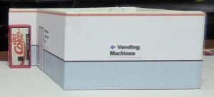
Photo 3 above: Empty shell now has windows and inner walls making this a rock solid and heavy plastic structure. Substructures being test fitted to the interior to be glued in later on and it’s definitely light proof. Notice the 3rd floor is still awaiting the 'inner walls'.
Various sub-buildings are being test fitted; the large square one in the top center of photo 3 is the “elevator/restroom housing” and wiring feed for lights will come through here. Inner buildings (sub-units) have Evergreen ½” tiles on the side toward the middle and various computer printed wallpaper on the sides. Each sub-unit was constructed of Evergreen plastic sheets and shapes and finished completely on the workbench before being installed.
The first floor ceiling and floor of the 2nd story is a sandwich of materials as thick as the wall brace that will support it; this space was designed originally for bulbs, later rethought to individual LEDs And, again, reduced to much more versatile SMD strips of LEDs. Sub-units on the 1st story will be:
1. a small ticket office,
2. the “elevator/restroom housing” for the wiring; and,
3. the most elaborate item on the floor, a combination car rental agency, dispatchers office for the rear loading bays, snack bar, and stairway to the 2nd floor.

Photo 4a above: Ceiling of the first floor showing 10 giant lights (5mm individual LEDs which need resistors). The first floor needs more lights which may be added later on.
Photo 4b below: Other side of the ceiling which shows the wiring and strengthening beams of the sandwich.

Next the flooring of the 2nd story was made from Evergreen ¼” scribed sheet sprayed the same light gray as the bottom floor. Several pieces were required and they are just lain in place as 2nd floor sub-units will be screwed to the ‘sandwich’ holding them securely in place. The left center of the floor is cut out as a large atrium which will run through to the roof for natural and artificial lighting to help illuminate the building. Sub units are test fitted and then removed for detailing latter on the work bench.
Photo 4c below: 2nd story floor is in place with the "elevator/restroom" housing holding it in place And, I am ready to work on the 2nd story ceiling sandwich.

2010-2011: building the second floor
The second floor ceiling/sandwich was constructed and test fitted in a similar manner; and, in the photo it is marked with an X for 15 individual LEDs. However, technology to the rescue and I’ve switched to SMD LEDs which will simplify both the installation and wiring. Lights will be added and photographed as soon as the SMDs arrive from China. Again, Evergreen ¼” scribed material was used for the flooring of the 3rd story. In Photo 5c, the preliminary wiring harness is done but not yet hooked up as I am experimenting with resistors to dim these extra bright lights a bit.

Photo 5a above: Ceiling of the 2nd floor showing the substituted SMDs in place of regular LEDs (10 strips were used, it's a big building)
Photo 5b below: Topside of the sandwich after the SMDs were installed showing the wiring mess not fully hooked up yet as I am experimenting with resistors to lower the brightness a bit.

End of Part 1 (to be continued)
(The forever project)
The idea for a large multi-mode transit center was born long, long ago; and, in a place far, far away (actually around 1974). In the late 50’s-60s HO scale buildings were quite frankly dinky and the biggest around were the Revell Bakery, Print shop and Engine House (all basically the same building) in plastic and some Suydam items in thick cardstock. I wanted a very large building to handle trains, streetcars and buses. TRANSPORT CENTRAL was an obvious choice for the name. Starting in 1975 many sets of ‘full size’ drawings were made as my ideas rapidly changed. It’s always pie in the sky for me at first and I envisioned a fully detailed and lighted building with large brass rectangular shapes at each corner with telescoping smaller shapes so each floor could be raised up and locked in place to view the inside. And, as usual, I quickly realized I’d never do this too elaborate idea and so scaled back the plans several times.
1975:
I wanted something modern and up to date that would not look 1900-1930 as many model railroaders liked for their era of operation at that time. Finally certain features looked more and more attractive and some scale floor plans were made. The design was strictly freelance on what I thought would look good and there is no particular building anywhere I was using as the basic model. Eventually a full size cardboard mock-up was made.
PHOTO 1 above: Showing its age, the cardboard mockup still exists after years of storage in an attic or basement. It’s leaning to the right, weakened by moisture absorption. The model as built so far doesn’t nearly match the mockup as reality often differs from dreams. But, this is where TRANSPORT CENTRAL started.
1993:
In the mid-90s I acquired about 20 Kibri plastic “brick” sheets at a good price (approximately 5” x 7” in size) from a dealer who couldn’t sell them. These sheets looked good; but, had one problem in that they varied in thickness being almost 1/8” thick at one end tapering down to around 1/16” at the other end. However, at this point I was gung-ho again and I transferred the dimensions from my drawings to the backside of the Kibri brick sheets; some dimensions had to be altered slightly to accommodate the size of these Kibri sheets. Then I laboriously carved all the fancy widow openings with an Xacto knife (53 of them). Many of the windows were purposefully large ‘picture window types’ to allow a view of what was meant later to be a super-detailed interior with lights. Carving through that thickness of material took forever, and made my fingers sore. Also I had to use a file to smooth out the irregularities in the openings. I glued the sheets together to form the building shell which had dimensions of 15-3/4” wide, 12-7/8” deep (long dimension including the overhang at the front right) and 4-7/16” tall (3 floors). I epoxied Plastruct tubing as vertical and horizontal wall braces to make the building more rigid and to eventually hold the 2nd, 3rd floors and the roof. The horizontal braces for the 2nd floor were wider than those for the 3rd floor to allow the “floors” to be easily dropped in place and to be removed if needed for interior work at later times. The bottom floor was made from Evergreen 1/8” scribed squares sheet (giant size sheet) sprayed light gray.
Photo 2a above: The empty shell was packed away for years as the real world intruded again as in making a living, raising a family, and a 1000 other things. What little modeling I did was strictly ready to run during this time. The wooden ruler on top of the building is 18" one and the metal ruler at the bottom is the General Steel HO scale ruler about 12" which will help you size the building.
Photo 2b below: A large, HO scale tour bus parked by the empty shell gives you a further indication of the large size of this model building
2005-2006:
I made my last move (I hope) into a new house. Kids are gone, and I’m retired so it’s time to get seriously busy on TRANSPORT CENTRAL before I need transporting to you know where. Next, the inner walls (Evergreen ½” squares) were clamped to the shell and window openings scribed from the outside to guarantee inner and outer windows openings matching up. Laboriously I hand carved and filed smooth 53 more window openings into the inner walls. Evergreen transparent sheets were cut and glued over window openings; and, the inner walls were painted “desert sand” and glued over the window material.
Photo 3 above: Empty shell now has windows and inner walls making this a rock solid and heavy plastic structure. Substructures being test fitted to the interior to be glued in later on and it’s definitely light proof. Notice the 3rd floor is still awaiting the 'inner walls'.
Various sub-buildings are being test fitted; the large square one in the top center of photo 3 is the “elevator/restroom housing” and wiring feed for lights will come through here. Inner buildings (sub-units) have Evergreen ½” tiles on the side toward the middle and various computer printed wallpaper on the sides. Each sub-unit was constructed of Evergreen plastic sheets and shapes and finished completely on the workbench before being installed.
The first floor ceiling and floor of the 2nd story is a sandwich of materials as thick as the wall brace that will support it; this space was designed originally for bulbs, later rethought to individual LEDs And, again, reduced to much more versatile SMD strips of LEDs. Sub-units on the 1st story will be:
1. a small ticket office,
2. the “elevator/restroom housing” for the wiring; and,
3. the most elaborate item on the floor, a combination car rental agency, dispatchers office for the rear loading bays, snack bar, and stairway to the 2nd floor.
Photo 4a above: Ceiling of the first floor showing 10 giant lights (5mm individual LEDs which need resistors). The first floor needs more lights which may be added later on.
Photo 4b below: Other side of the ceiling which shows the wiring and strengthening beams of the sandwich.
Next the flooring of the 2nd story was made from Evergreen ¼” scribed sheet sprayed the same light gray as the bottom floor. Several pieces were required and they are just lain in place as 2nd floor sub-units will be screwed to the ‘sandwich’ holding them securely in place. The left center of the floor is cut out as a large atrium which will run through to the roof for natural and artificial lighting to help illuminate the building. Sub units are test fitted and then removed for detailing latter on the work bench.
Photo 4c below: 2nd story floor is in place with the "elevator/restroom" housing holding it in place And, I am ready to work on the 2nd story ceiling sandwich.
2010-2011: building the second floor
The second floor ceiling/sandwich was constructed and test fitted in a similar manner; and, in the photo it is marked with an X for 15 individual LEDs. However, technology to the rescue and I’ve switched to SMD LEDs which will simplify both the installation and wiring. Lights will be added and photographed as soon as the SMDs arrive from China. Again, Evergreen ¼” scribed material was used for the flooring of the 3rd story. In Photo 5c, the preliminary wiring harness is done but not yet hooked up as I am experimenting with resistors to dim these extra bright lights a bit.
Photo 5a above: Ceiling of the 2nd floor showing the substituted SMDs in place of regular LEDs (10 strips were used, it's a big building)
Photo 5b below: Topside of the sandwich after the SMDs were installed showing the wiring mess not fully hooked up yet as I am experimenting with resistors to lower the brightness a bit.
End of Part 1 (to be continued)
Attachments
Last edited:


")


.jpg")
.jpg")
.jpg")


") . Hopefully the rest arrives before Christmas. I will be taking the building apart down to floor 1 a last time to install HO people in the halls, etc. and a photo will be posted, ditto for floor 2 and floor 3 at which time I hope I do not have to do this again for a long, long time. More soon I hope.
. Hopefully the rest arrives before Christmas. I will be taking the building apart down to floor 1 a last time to install HO people in the halls, etc. and a photo will be posted, ditto for floor 2 and floor 3 at which time I hope I do not have to do this again for a long, long time. More soon I hope.


