COMPUTER 2000 KITBASH

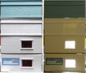
The best way to kitbash a structure that is both easy and impressive is to stack two or more of the same kit to make a taller structure. The buildings I chose is a Pola kit marketed as 4 or 5 different car showrooms by Pola, also imported by AHM, IHC, Model Power and others. I got two of the non-auto showroom versions, Computer 2000 (Pola) and Citibank (imported by Model Power, made by Pola). These are the same building.
The end result is a 4-story commercial building fully detailed on the inside with lights which will look good anywhere on your layout or diorama. Starting about 8 or 9 years ago I stopped gluing buildings up tight leaving at least the roof removable in case I needed to make repairs, change anything, or later add lights. And, in the case of multi-story buildings I now use 2-56 machine screws to hold the major components together. This way I can completely take a building apart for any sort of maintenance (and I find I often need to do so as often I add interiors and lights after a building shell has been finished). In the case of this kitbash I intended a full interior and lights to start with.
The Computer 2000 version of the building is one of Pola’s Master Models and had a detailed 1st floor showroom of computers for sale. I copied the signs that came with the kits to my computer and made various sized ones on the computer for use on the kit. Interior walls were first covered with black construction paper glued in place with silicone adhesive; on top of that wallpaper made on my computer printer was added. Various signs were glued on the walls.
I threw away the cheap blurry window material and substituted a 1-16” thick poured acrylic welders plastic protective piece cut to size. This is substantially stronger than is usual in kits and will not fall out if casually touched and wont be easily scratched. These lenses are crystal clear for viewing through by welders or modelers.
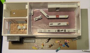
(above) The first floor is shown empty of people and after I had added “room” partitions and a paper interior from various photos found on the internet. A receptionist’s area behind the front door and in the upper left of the photo is an “elevator housing” where the wiring will go for the upper floors.
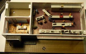
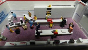
(above) This photo shows the 1st floor as finished complete with 10 +plus people and the interior with the Pola details. Bookcases and shelving were added from some Preiser kits. Items on the shelves were made from bits of scrap plastic from various structure sprues. Multi-colored items on some shelves to represent books were made from those tiny flat pieces of plastic that have “part numbers on them. These were filed flat (numbers removed) and glued together to form rows of books or products. Note white blocks of plastic with holes in them toward the corners of the building; this is where the screws will go to hold the next floor in place. People are glued in place with my favorite silicone glue, FixAll, available at most dollar stores in the US.
For people in this building I used some of the very cheap Chinese ones you can get on the internet. I had to do a little retouching of the paint on them but through the windows they look fine.
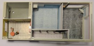
(above) The floor of the 2nd story is formed from the sidewalk of the second building kit. This is shown in the brownish color of the kit as a distinct line (in the very last photo)but could be painted to match the other exterior walls. The second story is the “showroom” from the Citibank kit and a major thing is turning the “entrance doorway” of the kit into a picture window for the small reception area by gluing in custom parts you make from leftover kit material from cutting out that window. Also, in the right rear of this floor's wall is an ‘overhead door’ for bringing things into an auto showroom. I cut this out into a picture window for one of the classrooms on this floor. Floor 2 was divided into 2 classrooms for teaching of computer subjects for customers and is shown empty in this photo. A short hallway fronts the rooms whose ‘windows partitions’ are empty frames with no ‘glass’ in them. Heavy acrylic welders protective lens were again used on the showroom windows to the outside.
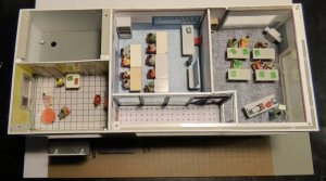
(above) The second floor as populated with people and detailed is in this photo. Tables, chairs, and vending machines in the receptionist/break room were from various such detail kits from Faller and Preiser. Again, note blocks of plastic with the holes which is were the screws will hold the 3rd floor in place. While I am not minutely detailing the interior the more you add, the better it will look from the outside
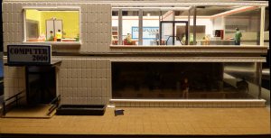
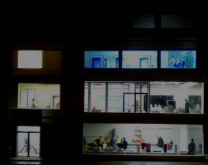
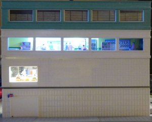
(above) The second floor from the outside (room light) showing how well the interior will show up when lighted in the finished building.
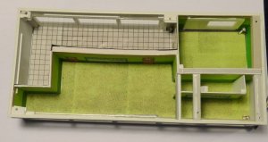
(above) The 3rd floor of this kit-bashing is the 2nd floor of the Citibank kit. It is now the workroom for the Computer 2000 business where they design, build and repair the various computers they sell. Most of the interior is in the rear, as the front is a hallway with numbered office doors (part of the Citibank interior). As this building will probably be view-able from both sides I put a full interior in the rear too.
(below) The next photo is the 3rd floor populated with people.
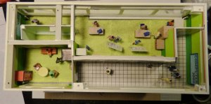
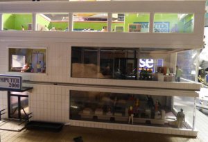
(above) Room light shows the interior of the 3rd floor from the outside rear. The floor is sitting backwards on top of floors 1 & 2 just for photo taking; and, will be facing the other way when the building is done.
Floor 4 which is the 2nd floor of the Computer 2000 building uses the simplified, and blocked, interior, of the Citibank building. These are the large windows blinds. For the window glazing I used Evergreen plastics clear sheet which also blurs the non-existent interior. This is substantially thicker than what comes in the kit; but, it is not perfectly clear which also blurs the non-existent interior..
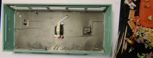
(above) The first photo shows the bare 4th floor with some 2-56 screws and a large LED (originally intended for illumination)). The second photo of this floor shows the only added interior – a receptionist area which will have no further detailing. The large conglomeration of plastic parts in the dead center of the floor are scrap sprue parts and some Evergreen shapes to provide a place to screw the roof (thru the central chimney) on to the building.
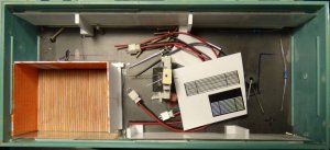
(above) Notice the four white (Evergreen shapes) poles which hold the window shades in place. This was done so if I ever get the notion I can take the ‘window blinds’ out and put in a visible interior. I doubt I’ll ever do this as three highly detailed floors wore me out some.
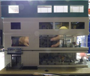
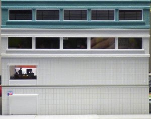
(above) An outside view of the 4th floor shows the simplistic detailing of the window blinds to block a detailed view of the interior. In the reflection of floor 2 windows in this photo you can see my fat hands holding the camera to take the picture. And, in the last photo of this series is the completed building from the outside BEFORE any interior details were put in taken after the shell was done but not screwed together.
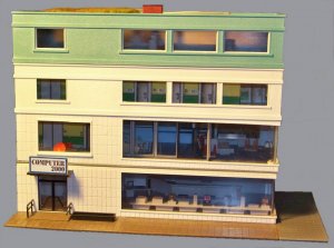
(above) A very early photo of the building before any details were added to the interior. Though I’ve left off describing most of the many intermediate steps of adding the interiors I think the photos will give you enough direction to do your own interior. It is amazing what you can do on you computer (and printer) toward detailing a building. I did floor coverings, wallpaper, signs, and other decorations on the computer, printed and cut them out; and, glued them in place.
I will add a part 2 to this kitbash thread shortly showing the wiring and lights which were added in about a year after the structure was finished. First I need to disassemble the building to get more photos of the lights and wiring. I did not take the photos with the idea of an article; but, they were handy as I used them to document the stages of construction of this kitbash. I will add more exterior views in the next part of the article of all the sides.
Any sort of large commercial building could be made from any too kits in this series including a 2-story auto showroom if you think about it.
Click a thumbnail to see a larger picture.
I had fun doing this one, Swamp Daddy

The best way to kitbash a structure that is both easy and impressive is to stack two or more of the same kit to make a taller structure. The buildings I chose is a Pola kit marketed as 4 or 5 different car showrooms by Pola, also imported by AHM, IHC, Model Power and others. I got two of the non-auto showroom versions, Computer 2000 (Pola) and Citibank (imported by Model Power, made by Pola). These are the same building.
The end result is a 4-story commercial building fully detailed on the inside with lights which will look good anywhere on your layout or diorama. Starting about 8 or 9 years ago I stopped gluing buildings up tight leaving at least the roof removable in case I needed to make repairs, change anything, or later add lights. And, in the case of multi-story buildings I now use 2-56 machine screws to hold the major components together. This way I can completely take a building apart for any sort of maintenance (and I find I often need to do so as often I add interiors and lights after a building shell has been finished). In the case of this kitbash I intended a full interior and lights to start with.
The Computer 2000 version of the building is one of Pola’s Master Models and had a detailed 1st floor showroom of computers for sale. I copied the signs that came with the kits to my computer and made various sized ones on the computer for use on the kit. Interior walls were first covered with black construction paper glued in place with silicone adhesive; on top of that wallpaper made on my computer printer was added. Various signs were glued on the walls.
I threw away the cheap blurry window material and substituted a 1-16” thick poured acrylic welders plastic protective piece cut to size. This is substantially stronger than is usual in kits and will not fall out if casually touched and wont be easily scratched. These lenses are crystal clear for viewing through by welders or modelers.

(above) The first floor is shown empty of people and after I had added “room” partitions and a paper interior from various photos found on the internet. A receptionist’s area behind the front door and in the upper left of the photo is an “elevator housing” where the wiring will go for the upper floors.

(above) This photo shows the 1st floor as finished complete with 10 +plus people and the interior with the Pola details. Bookcases and shelving were added from some Preiser kits. Items on the shelves were made from bits of scrap plastic from various structure sprues. Multi-colored items on some shelves to represent books were made from those tiny flat pieces of plastic that have “part numbers on them. These were filed flat (numbers removed) and glued together to form rows of books or products. Note white blocks of plastic with holes in them toward the corners of the building; this is where the screws will go to hold the next floor in place. People are glued in place with my favorite silicone glue, FixAll, available at most dollar stores in the US.
For people in this building I used some of the very cheap Chinese ones you can get on the internet. I had to do a little retouching of the paint on them but through the windows they look fine.

(above) The floor of the 2nd story is formed from the sidewalk of the second building kit. This is shown in the brownish color of the kit as a distinct line (in the very last photo)but could be painted to match the other exterior walls. The second story is the “showroom” from the Citibank kit and a major thing is turning the “entrance doorway” of the kit into a picture window for the small reception area by gluing in custom parts you make from leftover kit material from cutting out that window. Also, in the right rear of this floor's wall is an ‘overhead door’ for bringing things into an auto showroom. I cut this out into a picture window for one of the classrooms on this floor. Floor 2 was divided into 2 classrooms for teaching of computer subjects for customers and is shown empty in this photo. A short hallway fronts the rooms whose ‘windows partitions’ are empty frames with no ‘glass’ in them. Heavy acrylic welders protective lens were again used on the showroom windows to the outside.

(above) The second floor as populated with people and detailed is in this photo. Tables, chairs, and vending machines in the receptionist/break room were from various such detail kits from Faller and Preiser. Again, note blocks of plastic with the holes which is were the screws will hold the 3rd floor in place. While I am not minutely detailing the interior the more you add, the better it will look from the outside

(above) The second floor from the outside (room light) showing how well the interior will show up when lighted in the finished building.

(above) The 3rd floor of this kit-bashing is the 2nd floor of the Citibank kit. It is now the workroom for the Computer 2000 business where they design, build and repair the various computers they sell. Most of the interior is in the rear, as the front is a hallway with numbered office doors (part of the Citibank interior). As this building will probably be view-able from both sides I put a full interior in the rear too.
(below) The next photo is the 3rd floor populated with people.


(above) Room light shows the interior of the 3rd floor from the outside rear. The floor is sitting backwards on top of floors 1 & 2 just for photo taking; and, will be facing the other way when the building is done.
Floor 4 which is the 2nd floor of the Computer 2000 building uses the simplified, and blocked, interior, of the Citibank building. These are the large windows blinds. For the window glazing I used Evergreen plastics clear sheet which also blurs the non-existent interior. This is substantially thicker than what comes in the kit; but, it is not perfectly clear which also blurs the non-existent interior..

(above) The first photo shows the bare 4th floor with some 2-56 screws and a large LED (originally intended for illumination)). The second photo of this floor shows the only added interior – a receptionist area which will have no further detailing. The large conglomeration of plastic parts in the dead center of the floor are scrap sprue parts and some Evergreen shapes to provide a place to screw the roof (thru the central chimney) on to the building.

(above) Notice the four white (Evergreen shapes) poles which hold the window shades in place. This was done so if I ever get the notion I can take the ‘window blinds’ out and put in a visible interior. I doubt I’ll ever do this as three highly detailed floors wore me out some.

(above) An outside view of the 4th floor shows the simplistic detailing of the window blinds to block a detailed view of the interior. In the reflection of floor 2 windows in this photo you can see my fat hands holding the camera to take the picture. And, in the last photo of this series is the completed building from the outside BEFORE any interior details were put in taken after the shell was done but not screwed together.

(above) A very early photo of the building before any details were added to the interior. Though I’ve left off describing most of the many intermediate steps of adding the interiors I think the photos will give you enough direction to do your own interior. It is amazing what you can do on you computer (and printer) toward detailing a building. I did floor coverings, wallpaper, signs, and other decorations on the computer, printed and cut them out; and, glued them in place.
I will add a part 2 to this kitbash thread shortly showing the wiring and lights which were added in about a year after the structure was finished. First I need to disassemble the building to get more photos of the lights and wiring. I did not take the photos with the idea of an article; but, they were handy as I used them to document the stages of construction of this kitbash. I will add more exterior views in the next part of the article of all the sides.
Any sort of large commercial building could be made from any too kits in this series including a 2-story auto showroom if you think about it.
Click a thumbnail to see a larger picture.
I had fun doing this one, Swamp Daddy
Last edited:


