
This is how I designed the J-29 Tunnan model. Hopefully this can provide some insight into the process I used, and help others interested in designing their own models.
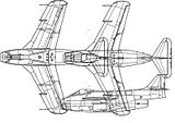
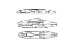
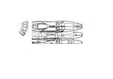
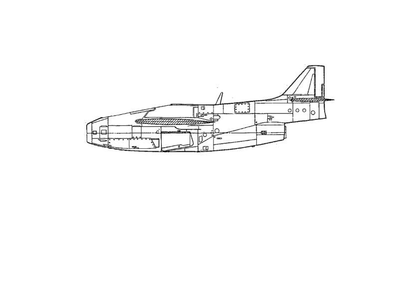
We start with three views of the aircraft to be used. In Photoshop, I have them each in different layers, and I've removed the white from the image, leaving just the black lines on a transparent background.

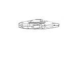
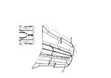
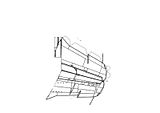
Next, I made a copy of the side view in a new layer, and erased the cockpit.

Because of the odd shape of the rear of this fighter's fuselage, I decided to take a different approach than usual. I drew a line across from the top of the fuselage to the top of the engine, because I decided to make the tail boom a seperate part.
Next, I erase the tail boom from this copy of the side view.
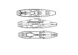
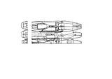
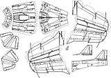
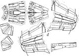
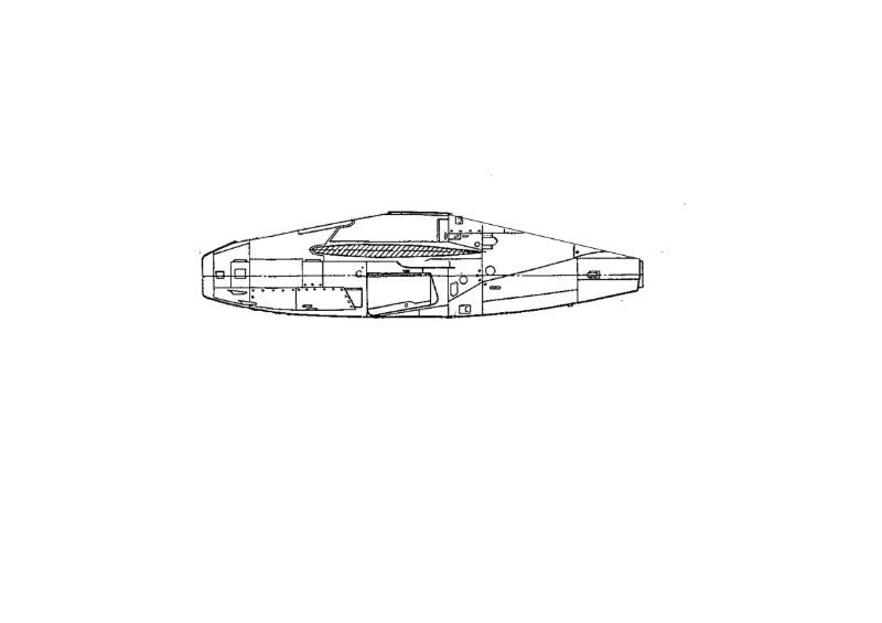
I then copy the fuselages from both the top and bottom views in their own layers. Layers are your friend when designing like this.
The bottom of the fuselage is where I generally prefer to make the model connect, so I cut the bottom view of the fuselage in half right down the center.
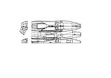
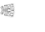
I found what I considered the first important angles in the fuselage, and seperated that part from each of the three views.
Using the top view as an anchor, I rotated the side view on top of it, matching the features of each as best I could.
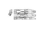
I then did the same thing with the bottom view.
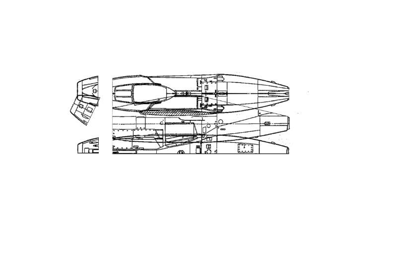
Then, I erased the overlapping edges and any conflicting features.
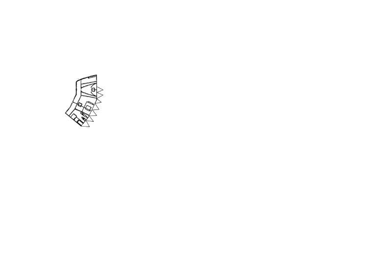
Then I "reinforced" the border lines and added tabs to the back of the nose.
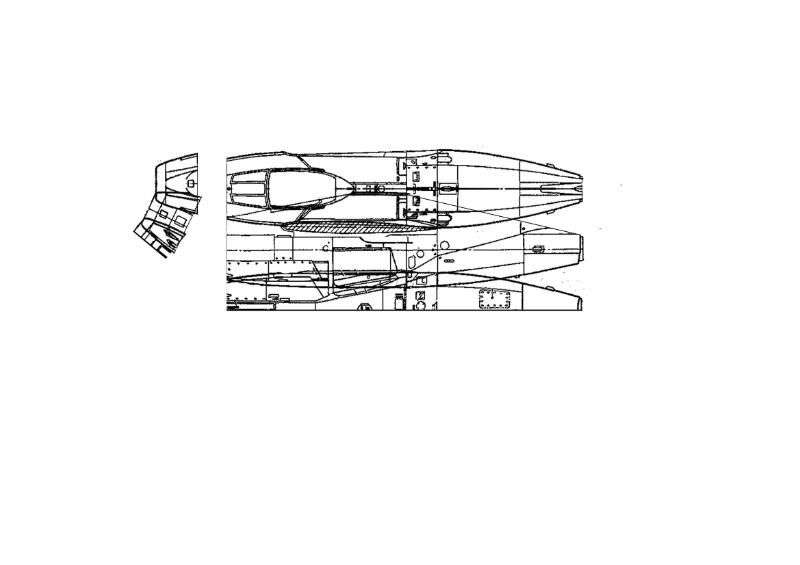
After merging those layers, I duplicated the resulting layer, and flipped it vertical.
Then I erase the overlapping edges again, and add the tab that connects the nose to itself.
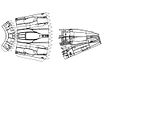
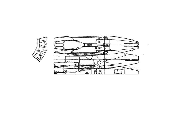
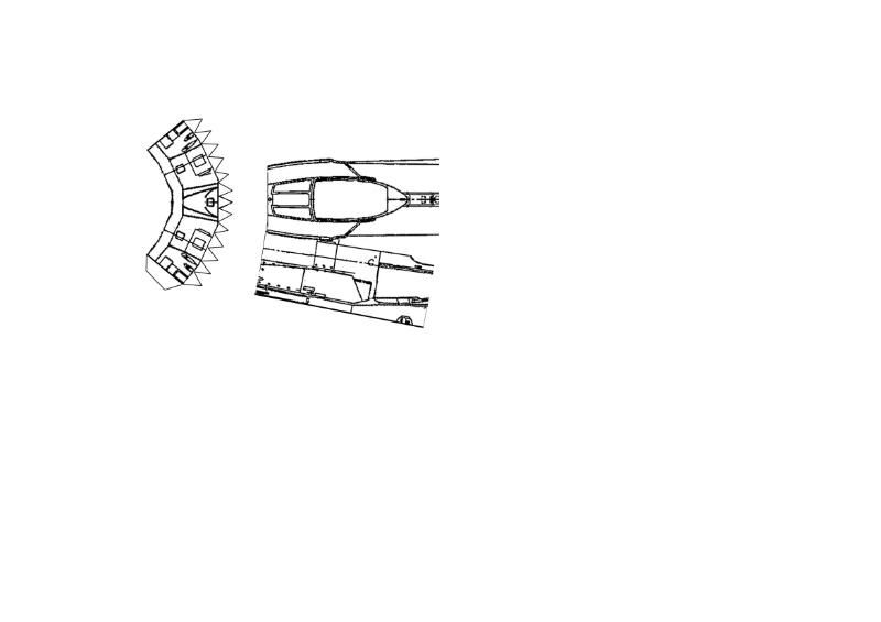
Then we pull those layers back up, and find the next instance of extreme angle, and cut them there.
Then I rotated the parts again, just as I did with the nose parts.
Just like before, get rid of the overlap.
Add the tabs, duplicate the layer, and flip verticle.
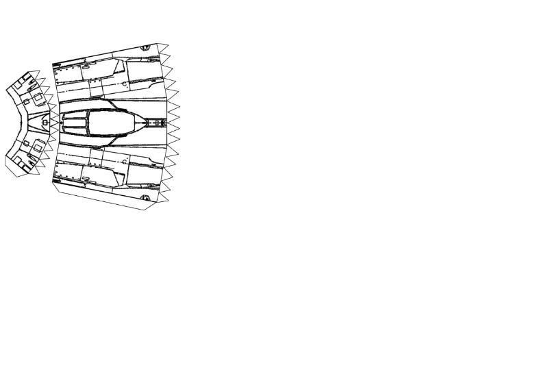
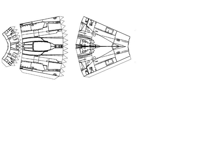
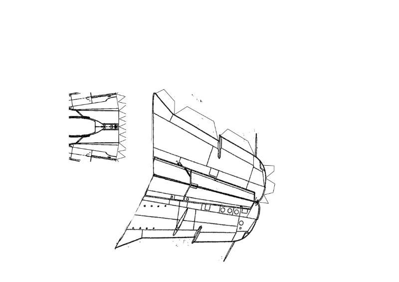
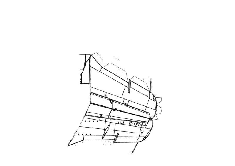
The same with the rear fuselage.
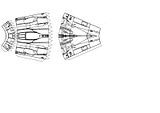
More of the same.
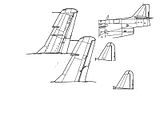
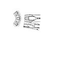
Next, make copies of one wing and one elevator from each view, plus the tail. Normally, I simply use the vertical stabilizer, but like I said, the boom on the J-29 makes it necssary to design the tail a different way.
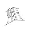
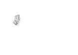
Take the two views of the wing, and flip one horizontal. Stick them together along the straightest edge possible. I also stretched them a little to make them thicker, to account for the curve of the wing when assembled.
I took this part of the fuselage to add to the wing, for connection.
I attached that part (after trimming it). It will help secure the wing to the fuselage.
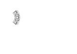
The same thing I did with the wing, I do with the horizontal stabilizers. Make sure to duplicate each and flip them, for the other side.
I removed the little fin and did the same thing for it. I also cut off the vertical stabilizer of the tail. Then I stretched the boom to make it wider.
Then I mirrored the boom. This will be bent and attach to the top of the fuselage during construction.
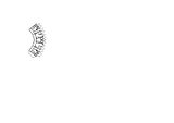
The vertical stabilizer gets the same treatment as the wings and elevators.
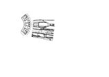
Then I just arrange them. I realized at this point that I'd forgotten the tabs on the elevators. Whoops.

The last part is the cockpit. I copied the cockpit and made it much wider.
Then I cut off the back and moved it back some, attaching the parts with tabs.
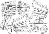
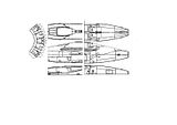
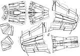
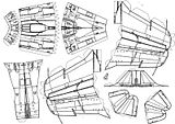
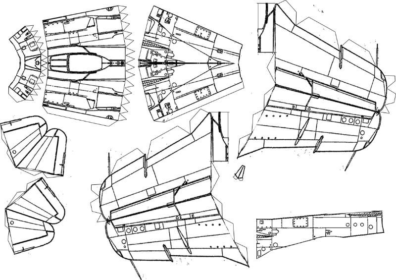
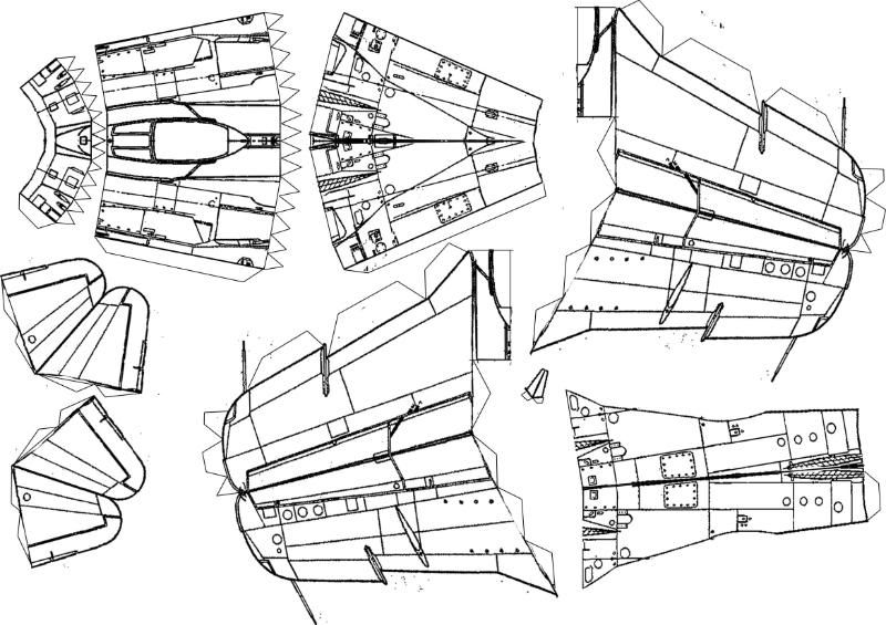
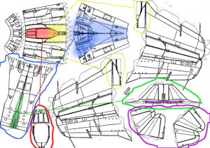
Here's the final layout of the parts.
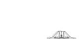
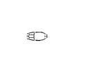
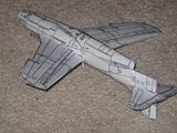
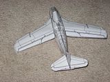
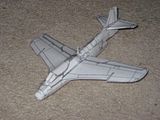
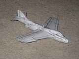
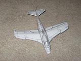
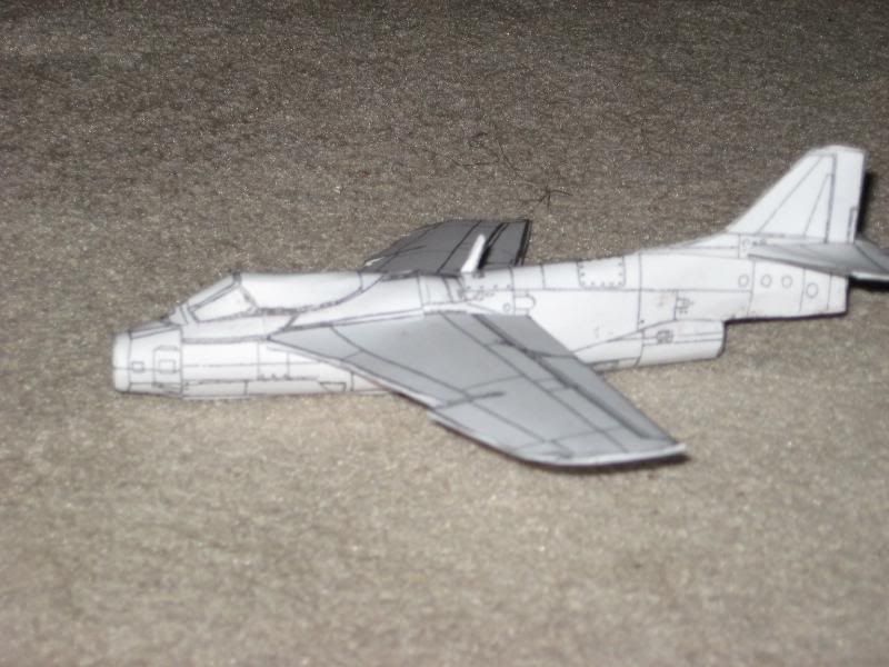
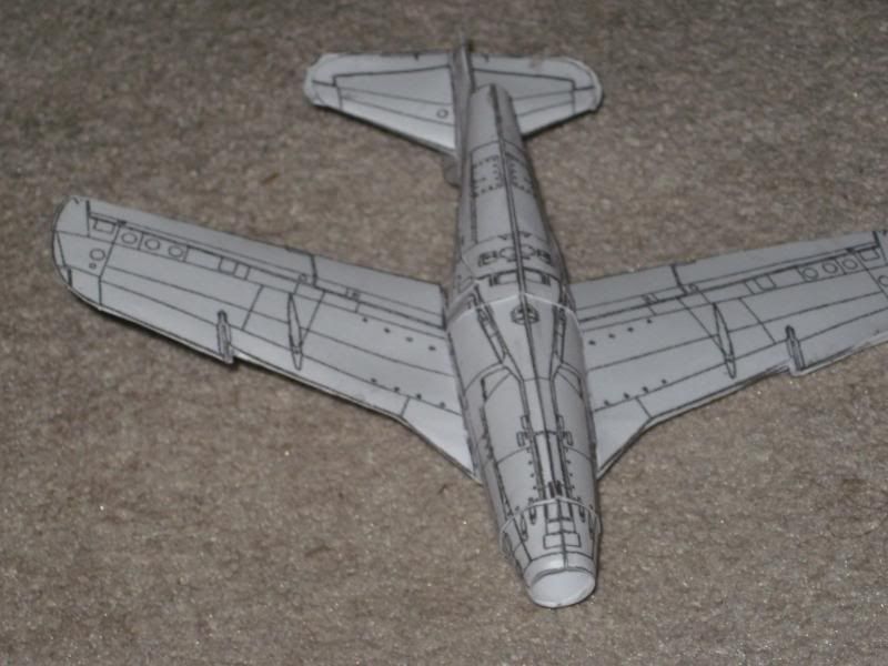
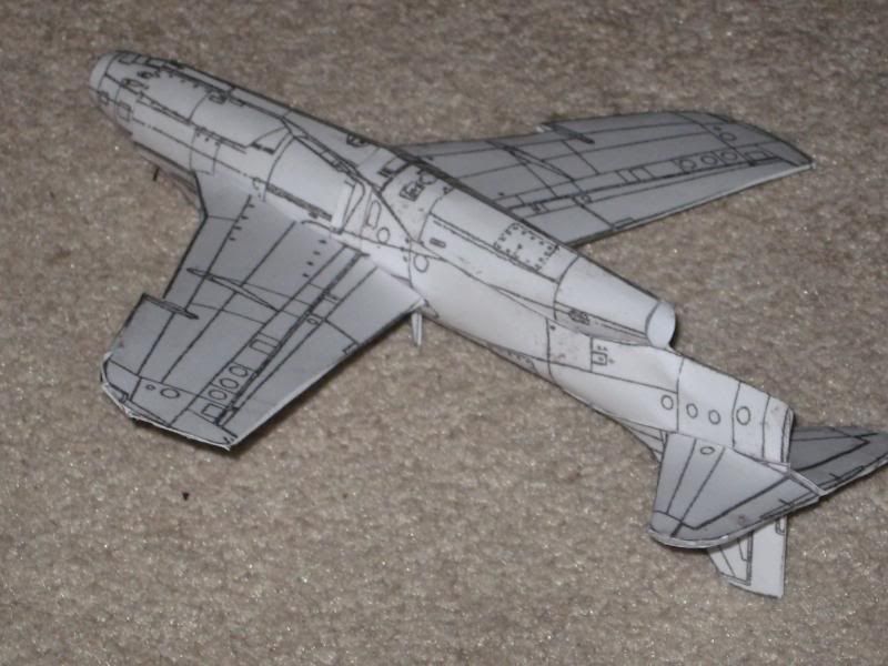
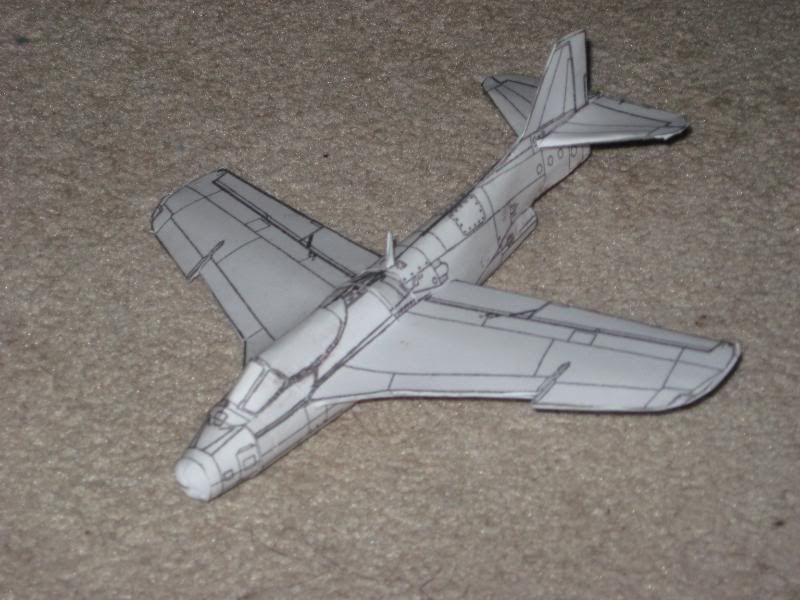
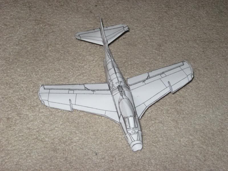
Here are some images of the final product:


Feel free to ask questions, post comments, etc. Let me know if some of this confuses you. I made this thread for all of you.

We start with three views of the aircraft to be used. In Photoshop, I have them each in different layers, and I've removed the white from the image, leaving just the black lines on a transparent background.

Next, I made a copy of the side view in a new layer, and erased the cockpit.
Because of the odd shape of the rear of this fighter's fuselage, I decided to take a different approach than usual. I drew a line across from the top of the fuselage to the top of the engine, because I decided to make the tail boom a seperate part.
Next, I erase the tail boom from this copy of the side view.

I then copy the fuselages from both the top and bottom views in their own layers. Layers are your friend when designing like this.

The bottom of the fuselage is where I generally prefer to make the model connect, so I cut the bottom view of the fuselage in half right down the center.
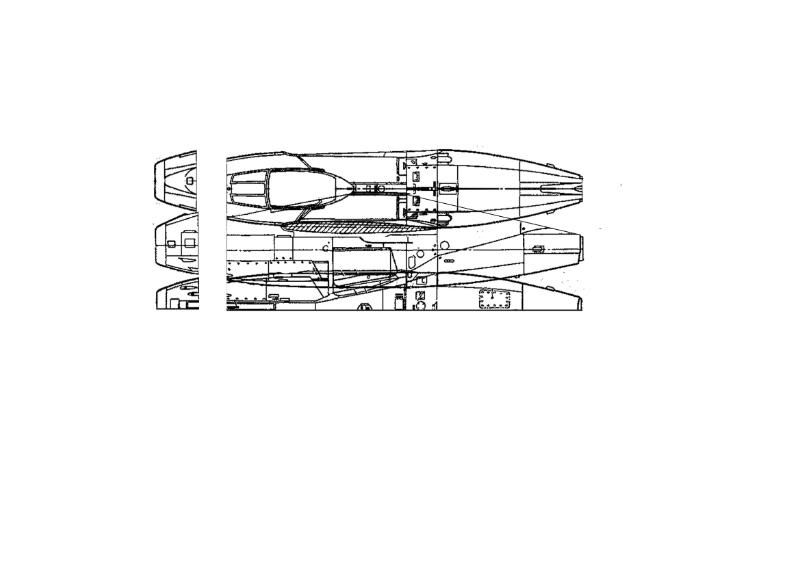
I found what I considered the first important angles in the fuselage, and seperated that part from each of the three views.
Using the top view as an anchor, I rotated the side view on top of it, matching the features of each as best I could.
I then did the same thing with the bottom view.
Then, I erased the overlapping edges and any conflicting features.
Then I "reinforced" the border lines and added tabs to the back of the nose.

After merging those layers, I duplicated the resulting layer, and flipped it vertical.

Then I erase the overlapping edges again, and add the tab that connects the nose to itself.

Then we pull those layers back up, and find the next instance of extreme angle, and cut them there.

Then I rotated the parts again, just as I did with the nose parts.
Just like before, get rid of the overlap.
Add the tabs, duplicate the layer, and flip verticle.

The same with the rear fuselage.
More of the same.

Next, make copies of one wing and one elevator from each view, plus the tail. Normally, I simply use the vertical stabilizer, but like I said, the boom on the J-29 makes it necssary to design the tail a different way.

Take the two views of the wing, and flip one horizontal. Stick them together along the straightest edge possible. I also stretched them a little to make them thicker, to account for the curve of the wing when assembled.
I took this part of the fuselage to add to the wing, for connection.
I attached that part (after trimming it). It will help secure the wing to the fuselage.

The same thing I did with the wing, I do with the horizontal stabilizers. Make sure to duplicate each and flip them, for the other side.
I removed the little fin and did the same thing for it. I also cut off the vertical stabilizer of the tail. Then I stretched the boom to make it wider.
Then I mirrored the boom. This will be bent and attach to the top of the fuselage during construction.

The vertical stabilizer gets the same treatment as the wings and elevators.
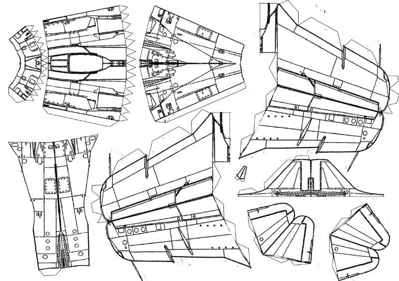
Then I just arrange them. I realized at this point that I'd forgotten the tabs on the elevators. Whoops.

The last part is the cockpit. I copied the cockpit and made it much wider.

Then I cut off the back and moved it back some, attaching the parts with tabs.
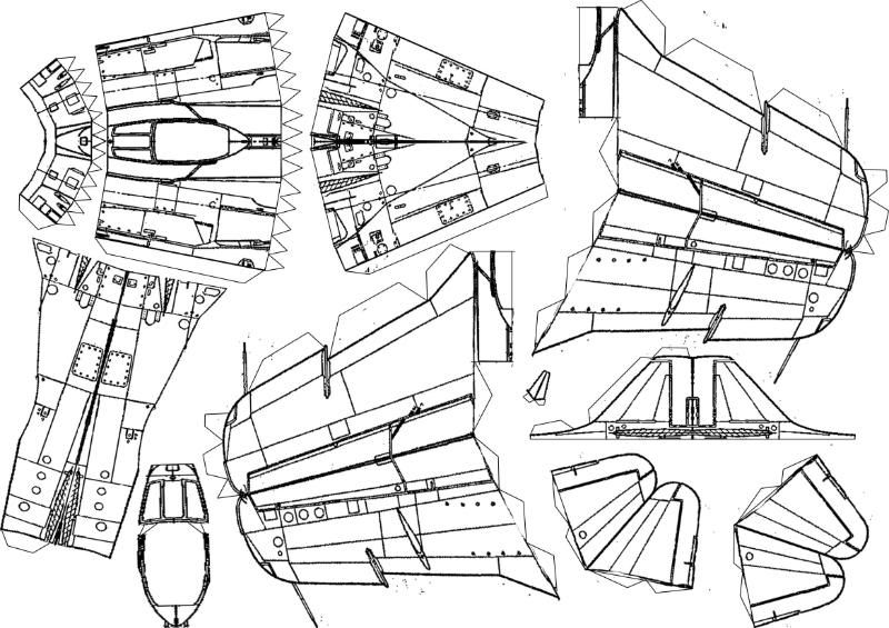
Here's the final layout of the parts.
Here are some images of the final product:


Feel free to ask questions, post comments, etc. Let me know if some of this confuses you. I made this thread for all of you.
")