Part 1: Planning and Building Your 3D Model
Planning
Before you create any 3D objects, plan out what your end model will be. Find some pictures or photos of it if you can, or if it's a self created item, draw it out on paper or in a drawing app a few times to get a feel for the real 3D shape. Some people make mockups in LEGO or some other building material first.
Once you have a feel for how the model will look and feel, think about what it will be used for. Will it be handled a lot? Will it be a display model? Will it be something to hang on the wall or give to the kids to play with? Each of these options opens up different issues. If it is to be handled a lot (such as a gaming miniature) then it will need to be sturdy and might need internal supports, for example.
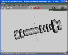
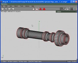
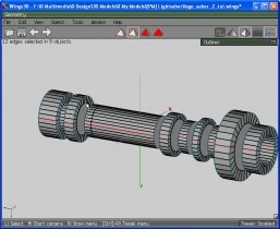
I'm using a human-scale model of a LEGO lightsaber handle for this tutorial - the intent would be for it to be used as a prop or a toy, and maybe have a mockup lightsaber blade put on it, or maybe some lights fitted inside. It will therefore need to be quite sturdy. Note that I'm British, but I will be annoyingly consistent in spelling "saber" with the "e" before the "r" because a lightsaber is an American film-maker's invention and the canonical spelling of the word is the American way. Sorry about that, UK readers.
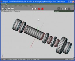
In planning for any prop, durability is to be considered. With this particular model, the fact that it is basically a cylinder means that it will be quite sturdy on its own. Breaking the model down into various sized cylinders (a new complete cylinder for each change in diameter on the model) adds even more sturdiness and makes it a nice, simple, quick build. I like simple.
Step one, then, is to find or draw a 2D flat representation of the model from the three cardinal directions (top, left and front) that are represented by the three main views in Wings 3D. You can obtain bottom, rear and left elevations as well if desired, but for this model they're not necessary. In fact, this model only needs a side view, as the top view is exactly the same and the front view is a cylinder.
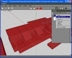
Open Wings3D, right click on the empty workspace and select "Image Plane".
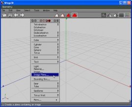
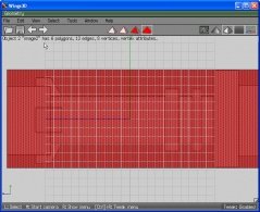
Using the dialog, find your side view and select it - it will load into a flat "plane" which will by default show to the X axis. Select the Image Plane, making sure that Object selection mode is active (that's the last of the block of 4 pyramids at the top of the workspace)
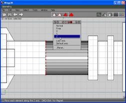
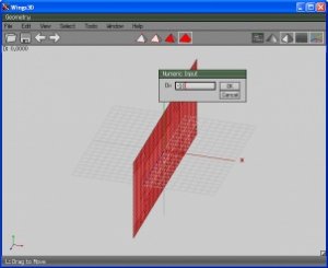
Rotate the view a bit (using the middle mouse button with a bit of movement) so that you can see the relative position of the selected plane. Right click in the workspace, select "Move" then "X". Moving your mouse will move the Image Plane back and forward along the X axis. Press "Tab" on the keyboard and type "-10" into the Numeric Input box then press "Enter" - this will move the plane 10 units to the rear (left) of the workspace.
You have the option at this point of scaling the Image Plane to use Wings' grid as a scale guide to the finished article. It isn't actually all that important at this point because the exported texture at the end of this process will be on either a 512, 1024, 2048 or 4096 pixel square and you'll just have to scale it again in your drawing app later. However, on some projects I have been known to create a 1x1 square "inset" in one face of the model to give me a scale guide for later. The idea is to use that square in your drawing app, using centimetres or inches or whatever as your scale, make the inset guide in your model be equal to 1x1 in your drawing later. I won't be going back to this in the tutorial, but you can ask for a few more hints about it later if you like.
This part of the tutorial is more of a quick overview of modelling with primitive shapes in Wings3D. If you already know all this stuff then you should either be able to work through it really easily or just skip it and go to either part 2 or part 3. Up to you really.
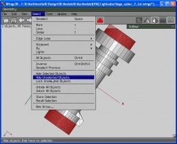
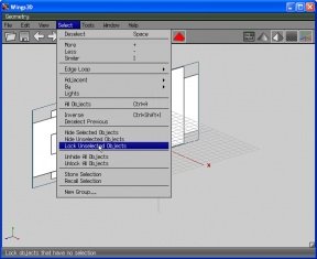
Press "Space" on the keyboard or click anywhere on the empty part of the toolbar to unselect all objects. Choose "Select" from the menu and click on "Lock Unselected Objects". This will lock the image plane in place so that it can't be selected using the mouse and leave us free to work on the actual model.
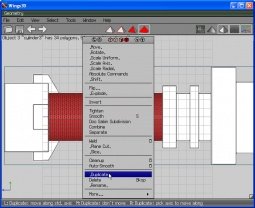
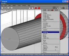
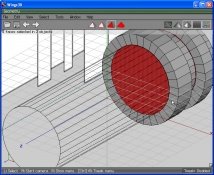
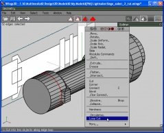
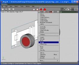
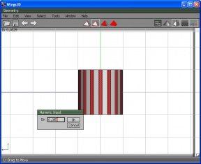
Now to the saber itself. Right click in the workspace and select Cylinder. As if by magic one appears. Switch to Edge select mode (second pyramid on the toolbar) and select all the vertical edges of the cylinder. An easy way to do this is to press "x" on the keyboardto view the model along the X axis and go into orthagonal display mode (second of the icons at the right of the toolbar). Once the edges are selected (there should be 16 of them) right click and select "Bevel". Press "Tab" on the kb and enter "0.095" in the Numeric Input box then press Enter.
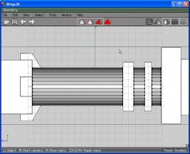
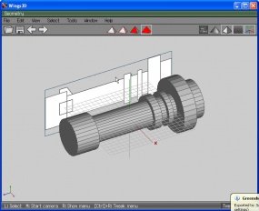
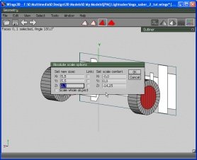
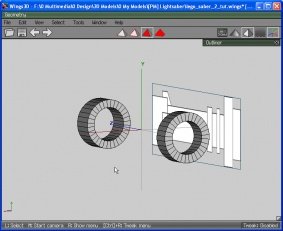
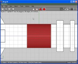
Click on the Object mode pyramid to select the whole cylinder. Right click and select "Rotate" then "X" then press the "TAB" key and enter "90" into the Numeric Input box. This aligns the cylinder with the Z axis as shown below (viewing directly along the X axis). Right click, select "Scale Uniform" and resize the cylinder until it is the same height as the drawing behind. As stated, viewing directly along the X axis will make it easier to see when the cylinder is the right size. It doesn't have to be exact.
Planning
Before you create any 3D objects, plan out what your end model will be. Find some pictures or photos of it if you can, or if it's a self created item, draw it out on paper or in a drawing app a few times to get a feel for the real 3D shape. Some people make mockups in LEGO or some other building material first.
Once you have a feel for how the model will look and feel, think about what it will be used for. Will it be handled a lot? Will it be a display model? Will it be something to hang on the wall or give to the kids to play with? Each of these options opens up different issues. If it is to be handled a lot (such as a gaming miniature) then it will need to be sturdy and might need internal supports, for example.
I'm using a human-scale model of a LEGO lightsaber handle for this tutorial - the intent would be for it to be used as a prop or a toy, and maybe have a mockup lightsaber blade put on it, or maybe some lights fitted inside. It will therefore need to be quite sturdy. Note that I'm British, but I will be annoyingly consistent in spelling "saber" with the "e" before the "r" because a lightsaber is an American film-maker's invention and the canonical spelling of the word is the American way. Sorry about that, UK readers.
In planning for any prop, durability is to be considered. With this particular model, the fact that it is basically a cylinder means that it will be quite sturdy on its own. Breaking the model down into various sized cylinders (a new complete cylinder for each change in diameter on the model) adds even more sturdiness and makes it a nice, simple, quick build. I like simple.
Step one, then, is to find or draw a 2D flat representation of the model from the three cardinal directions (top, left and front) that are represented by the three main views in Wings 3D. You can obtain bottom, rear and left elevations as well if desired, but for this model they're not necessary. In fact, this model only needs a side view, as the top view is exactly the same and the front view is a cylinder.
Open Wings3D, right click on the empty workspace and select "Image Plane".

Using the dialog, find your side view and select it - it will load into a flat "plane" which will by default show to the X axis. Select the Image Plane, making sure that Object selection mode is active (that's the last of the block of 4 pyramids at the top of the workspace)

Rotate the view a bit (using the middle mouse button with a bit of movement) so that you can see the relative position of the selected plane. Right click in the workspace, select "Move" then "X". Moving your mouse will move the Image Plane back and forward along the X axis. Press "Tab" on the keyboard and type "-10" into the Numeric Input box then press "Enter" - this will move the plane 10 units to the rear (left) of the workspace.

You have the option at this point of scaling the Image Plane to use Wings' grid as a scale guide to the finished article. It isn't actually all that important at this point because the exported texture at the end of this process will be on either a 512, 1024, 2048 or 4096 pixel square and you'll just have to scale it again in your drawing app later. However, on some projects I have been known to create a 1x1 square "inset" in one face of the model to give me a scale guide for later. The idea is to use that square in your drawing app, using centimetres or inches or whatever as your scale, make the inset guide in your model be equal to 1x1 in your drawing later. I won't be going back to this in the tutorial, but you can ask for a few more hints about it later if you like.
This part of the tutorial is more of a quick overview of modelling with primitive shapes in Wings3D. If you already know all this stuff then you should either be able to work through it really easily or just skip it and go to either part 2 or part 3. Up to you really.
Press "Space" on the keyboard or click anywhere on the empty part of the toolbar to unselect all objects. Choose "Select" from the menu and click on "Lock Unselected Objects". This will lock the image plane in place so that it can't be selected using the mouse and leave us free to work on the actual model.

Now to the saber itself. Right click in the workspace and select Cylinder. As if by magic one appears. Switch to Edge select mode (second pyramid on the toolbar) and select all the vertical edges of the cylinder. An easy way to do this is to press "x" on the keyboardto view the model along the X axis and go into orthagonal display mode (second of the icons at the right of the toolbar). Once the edges are selected (there should be 16 of them) right click and select "Bevel". Press "Tab" on the kb and enter "0.095" in the Numeric Input box then press Enter.

Click on the Object mode pyramid to select the whole cylinder. Right click and select "Rotate" then "X" then press the "TAB" key and enter "90" into the Numeric Input box. This aligns the cylinder with the Z axis as shown below (viewing directly along the X axis). Right click, select "Scale Uniform" and resize the cylinder until it is the same height as the drawing behind. As stated, viewing directly along the X axis will make it easier to see when the cylinder is the right size. It doesn't have to be exact.


