

You might be wondering what the metal fencing in the background is all about? Well, we had rabbits, and this is one of them. His name's Baxter 

All the wiring had to be marked accordingly because there are a surprising number of them. I had to design the circuit diagram for the model prior to doing any wiring. I studied the movie to see exactly what happened when Henry operated the machine. The disk speed and rotations. The number and color of the lights and specifically where they were located on the Time Machine. Trying to get a picture in your mind of how it would really work, or of course intend to work as we are dealing with scfi")

This is the boss for the main disk. It has a coupling to connect with the motor. The motor has an inline planetary gearbox and works great for this application. Its off an old robot model I had.

This is the wiring loom from the console. I made the ends of the console from mat clear printable film. It works great on my old Kodak inkjet printer. I wanted a good amount of light to show through these end caps. By the way, the date has some significance to me.

I had to make a "snake" to draw the wires through the paper railings. I couldn't just push it all through as it would snag on the joins in the paper railings. A piece of bowden cable from a R/C model push-rod worked really well for all the model.

The copper wires gave the railings more rigidity too. I used to use this type of wire for the "round-the-pole electric model planes" back in the day. There were to many wires to easily pass through one side of the railings so I had to split them into two looms.

Oh, here's the nuts and bolts I installed to make it look more realistic. The blue painters tape in the background works great for marking all the wires. I just cut it into small pieces and wrapped them around the ends of each wire, and used a black Sharpie to tag it.

As I look at these photos, it brings back a lot of nostalgia I really got lost in it when I built this.

Here's the main horizontal handrail all built up. You can see some of the markings for the parts placement show up a lot because of the scale-up. I was thinking of spraying the railings gold but that would make them inconsistent with the rest of the model. Also, the forced shading would all be lost with just a flat paint applied.

Some of the decorations. All the edges had to be painted to make them look better.

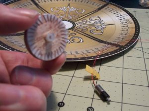
Here's the tiny motor with the prop-shaft attached with the rubber coupling. This drives the disk.

I had to use one of my old micro-servos to get the amplifier controller PCB. The motor and gearbox for the servo was too big to use for the model, so I just kept those parts as spares. The servo requires a pulse-train to tell the motor to turn, the direction and the variable speed.:Coffee: The death of one of my servos!

Here's the bit I need! Some fine soldering work needed here! This setup would work good for a small R/C boat motor/speed control combo.

All the wiring had to be marked accordingly because there are a surprising number of them. I had to design the circuit diagram for the model prior to doing any wiring. I studied the movie to see exactly what happened when Henry operated the machine. The disk speed and rotations. The number and color of the lights and specifically where they were located on the Time Machine. Trying to get a picture in your mind of how it would really work, or of course intend to work as we are dealing with scfi
This is the boss for the main disk. It has a coupling to connect with the motor. The motor has an inline planetary gearbox and works great for this application. Its off an old robot model I had.
This is the wiring loom from the console. I made the ends of the console from mat clear printable film. It works great on my old Kodak inkjet printer. I wanted a good amount of light to show through these end caps. By the way, the date has some significance to me.
I had to make a "snake" to draw the wires through the paper railings. I couldn't just push it all through as it would snag on the joins in the paper railings. A piece of bowden cable from a R/C model push-rod worked really well for all the model.
The copper wires gave the railings more rigidity too. I used to use this type of wire for the "round-the-pole electric model planes" back in the day. There were to many wires to easily pass through one side of the railings so I had to split them into two looms.
Oh, here's the nuts and bolts I installed to make it look more realistic. The blue painters tape in the background works great for marking all the wires. I just cut it into small pieces and wrapped them around the ends of each wire, and used a black Sharpie to tag it.
As I look at these photos, it brings back a lot of nostalgia
I really got lost in it when I built this. Here's the main horizontal handrail all built up. You can see some of the markings for the parts placement show up a lot because of the scale-up. I was thinking of spraying the railings gold but that would make them inconsistent with the rest of the model. Also, the forced shading would all be lost with just a flat paint applied.
Some of the decorations. All the edges had to be painted to make them look better.
Here's the tiny motor with the prop-shaft attached with the rubber coupling. This drives the disk.
I had to use one of my old micro-servos to get the amplifier controller PCB. The motor and gearbox for the servo was too big to use for the model, so I just kept those parts as spares. The servo requires a pulse-train to tell the motor to turn, the direction and the variable speed.:Coffee: The death of one of my servos!
Here's the bit I need!
Some fine soldering work needed here! This setup would work good for a small R/C boat motor/speed control combo.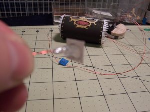


 all done!
") I used to work as an electronics engineer back in the UK for 10 years or more. All these old skills seem to help with my own projects now. We used to build special purpose machines using robotics. I used to design and program the control systems. This was from 1980 thru 1990. We also used to build and etch custom PCBs for certain requirements. It was a lot of fun, and I was able to learn lot from some from the awesome engineers I worked with,
I used to work as an electronics engineer back in the UK for 10 years or more. All these old skills seem to help with my own projects now. We used to build special purpose machines using robotics. I used to design and program the control systems. This was from 1980 thru 1990. We also used to build and etch custom PCBs for certain requirements. It was a lot of fun, and I was able to learn lot from some from the awesome engineers I worked with, thumbsup