"Aerodynamics are for people who can't build engines." ~ Enzo Ferrari
With the bottom engines basically complete, I started on the top engines.
The top engines are a little more complex and the build procedure is different.
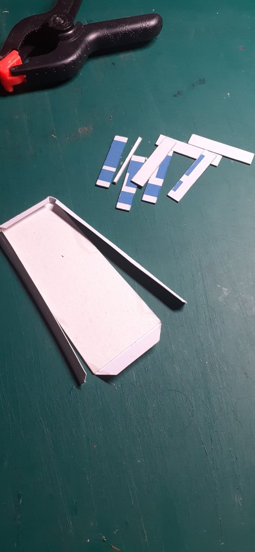
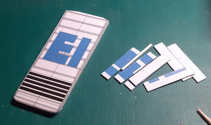
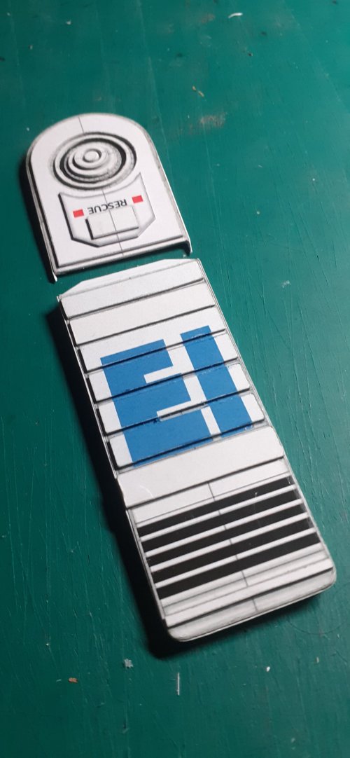
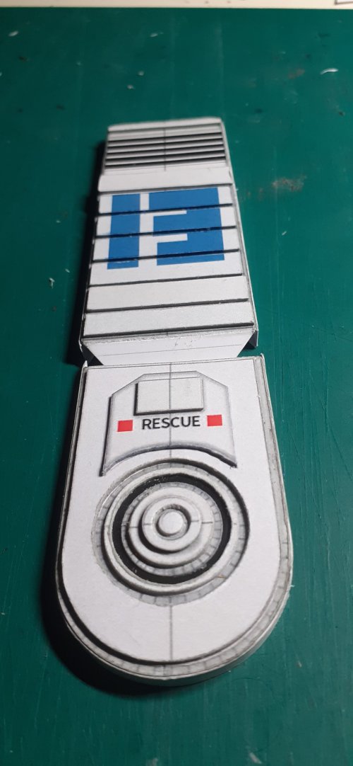
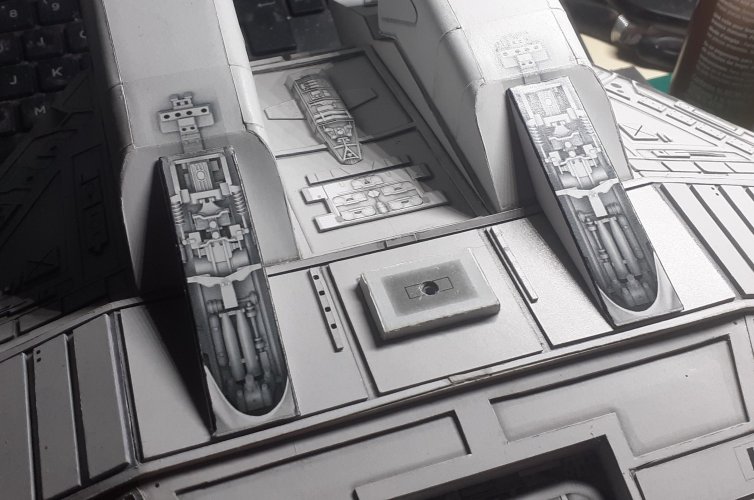
One thing to note here, when cutting out the floor of the engine, the part to the right in the pics below, be aware that the edge of the part under the indent has two angled planes and is not a straight cut. It is easy to miss this and if you do, it will create problems with alignment.
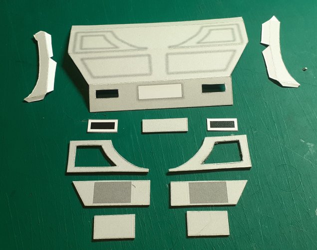
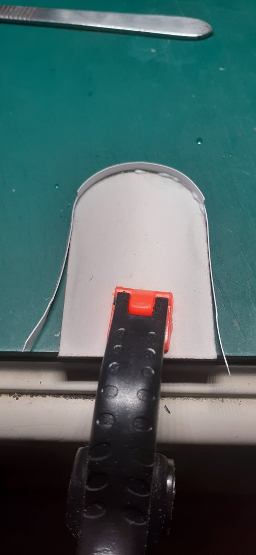
The main panels were cut out, edge coloured and pre-shaped..
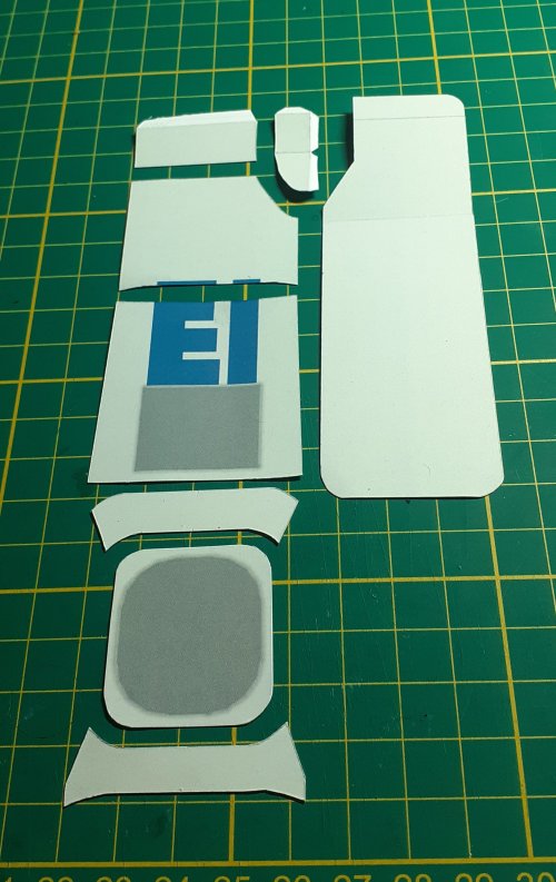
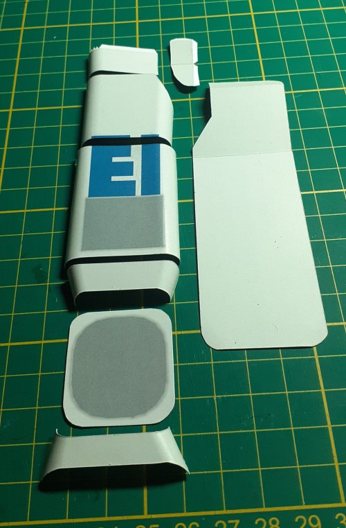
In a similar fashion to the bottom engines, I back-tabbed the parts where necessary.
The exhaust cowling was made up first. When fitting the exhaust mounting plate make sure it is sitting perfectly square to all faces of the engine.
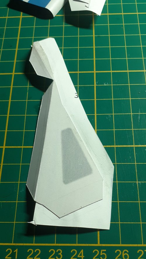
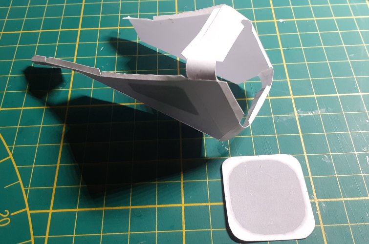
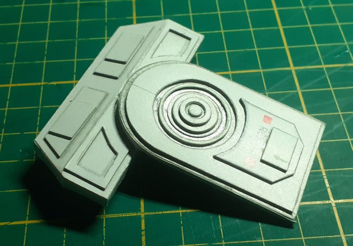
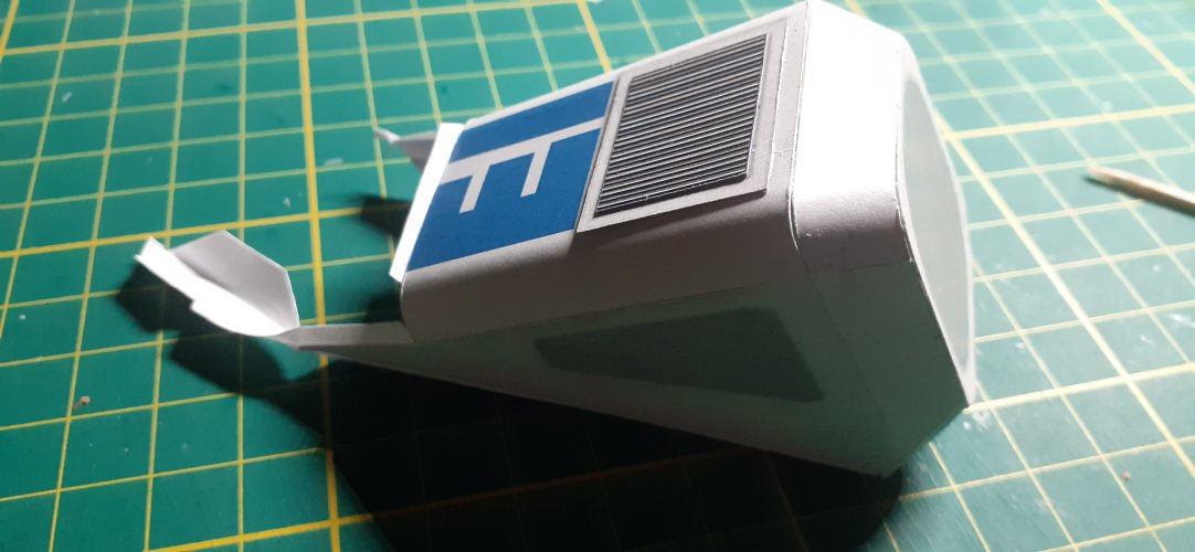
The main top panel was added next. I made up the grill detail panel and attached it to the main panel while I still had access, to glue it down firmly.
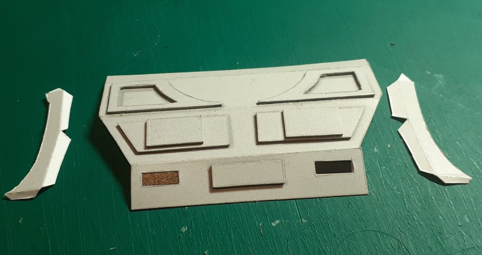
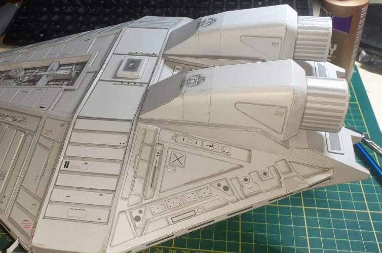
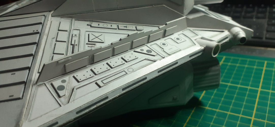
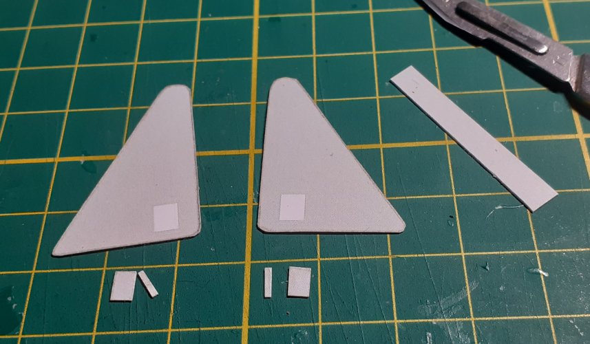
I made up the triangular side detail panels for the bottom and top engines.
The detail panels on the top engines are smaller than the bottom engines.
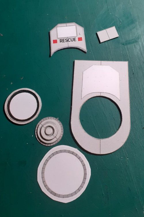
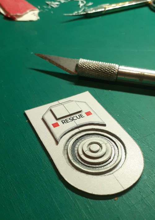
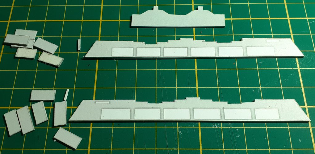
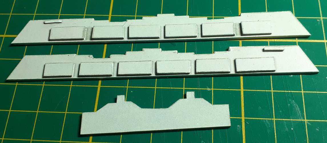
There is a fault in the template for these parts. The detail pieces that fit onto the small square of the side panel are not correct for the lower engines. They are too small!! The designer obviously copied the detail pieces from the top engines, but did not scale them up to fit the larger side panels of the bottom engines.
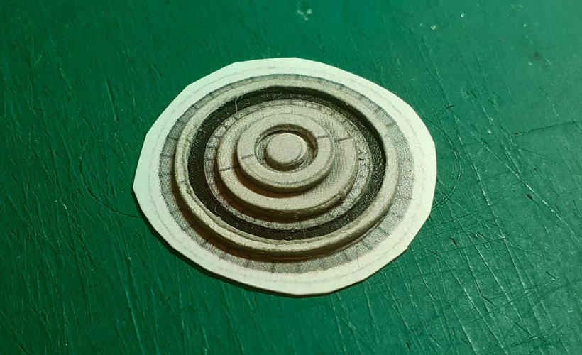
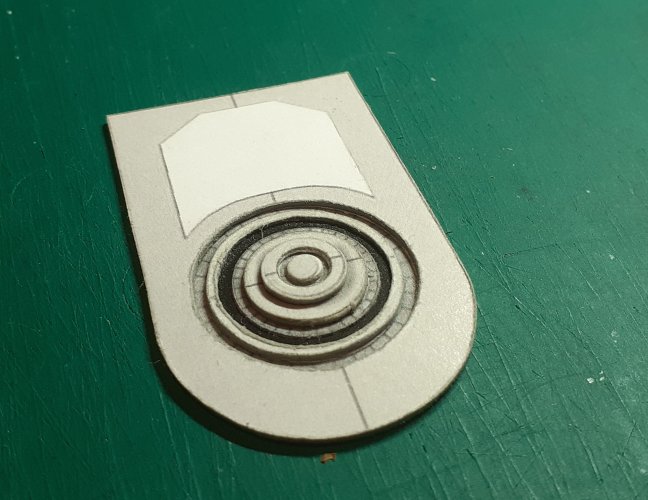
So, I made some new detail parts from spare card that fit correctly.
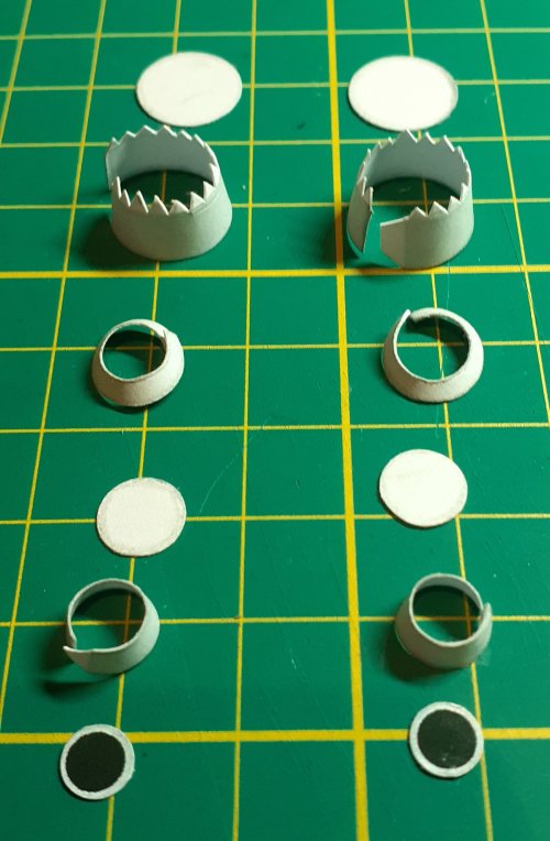
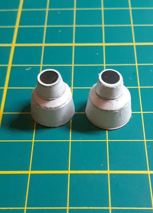
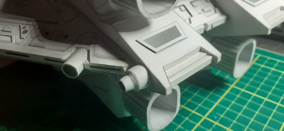
At this stage, I stopped adding panels and fitted the engine nozzles to the top and bottom engines. The reason for this, better access for gluing.
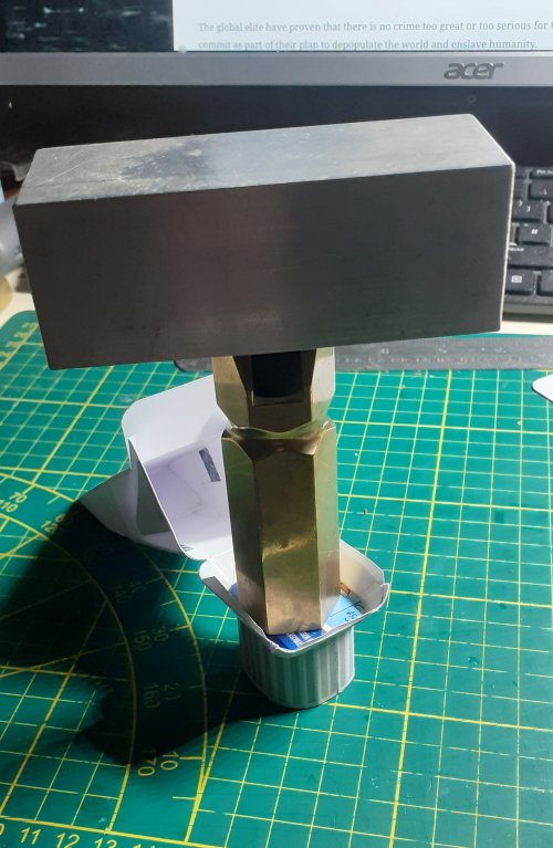
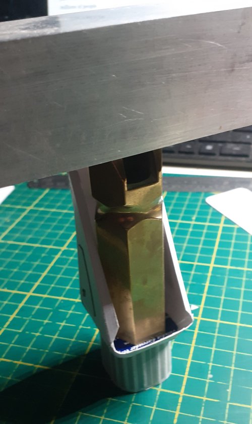
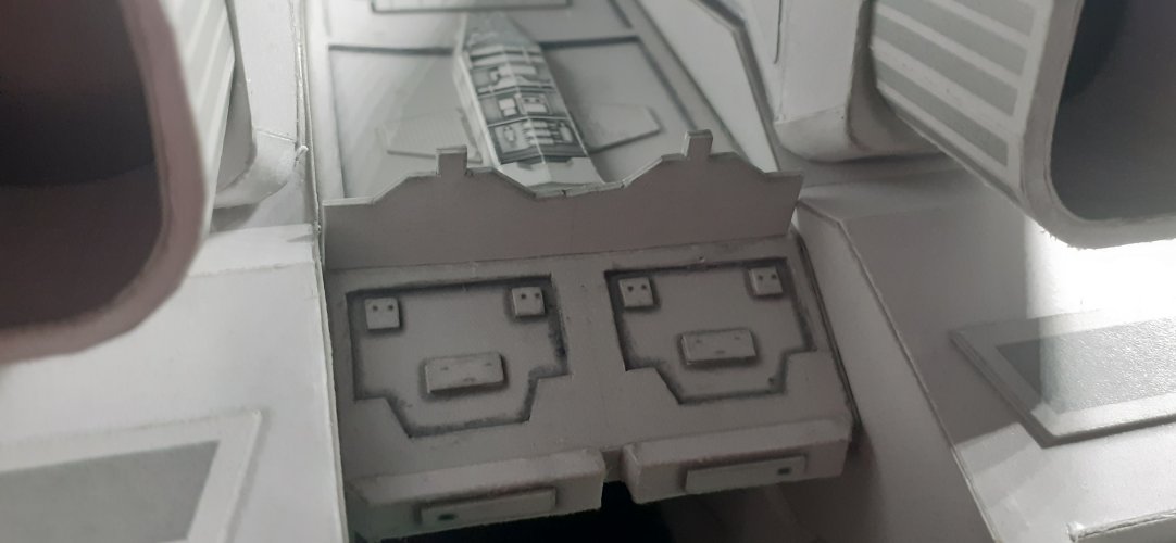
The front of the bottom engines was closed up, again making sure everything is nice and square with no twists.
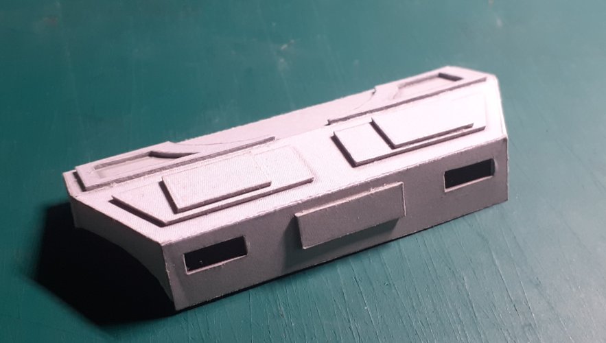
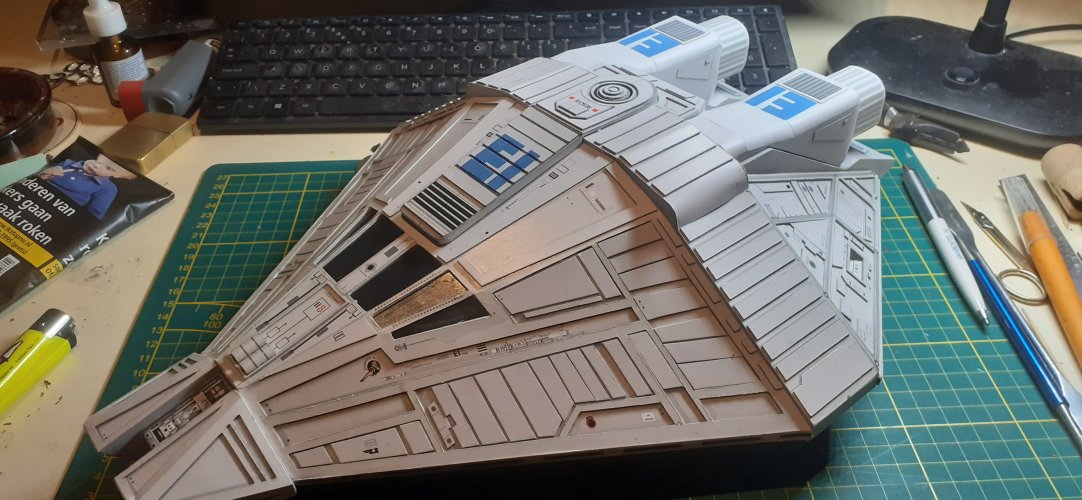
The remaining panels for the top engines were carefully added, checking for squareness continuously.
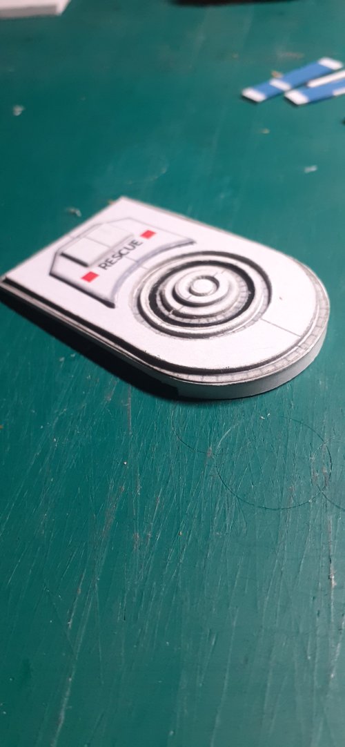
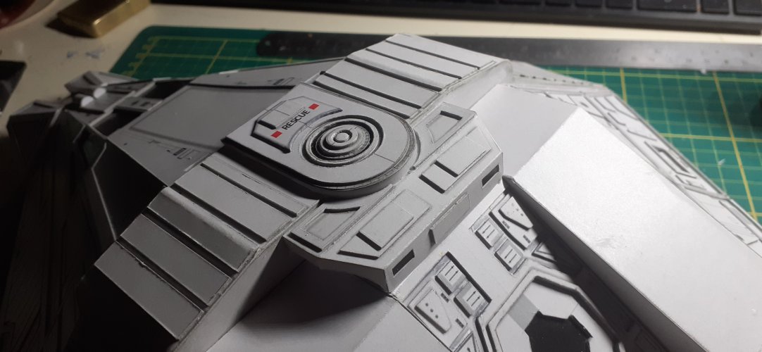
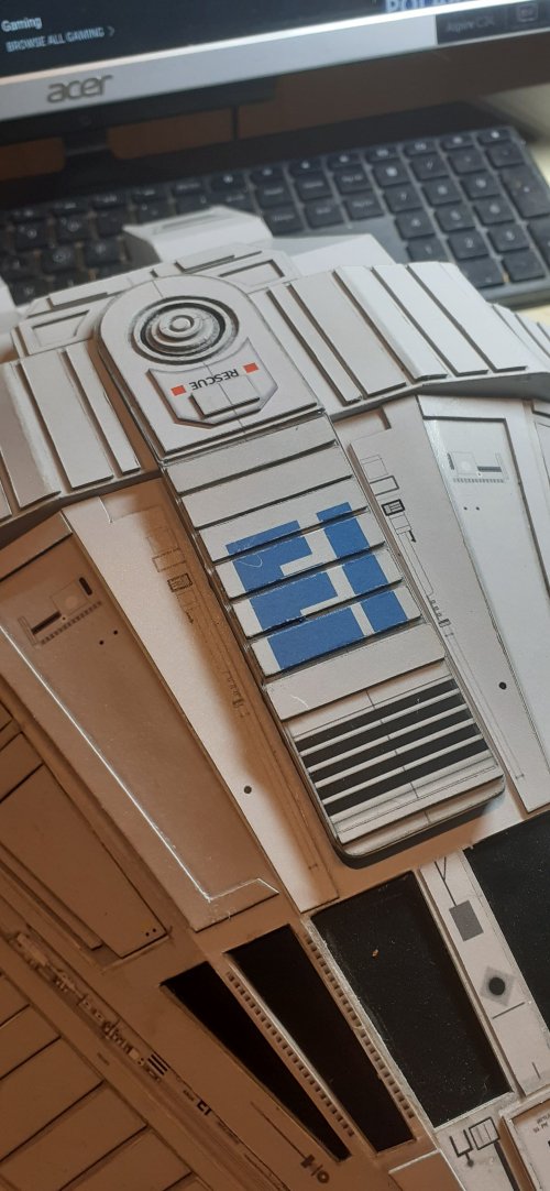
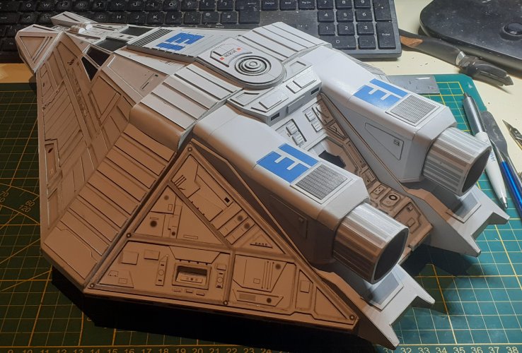
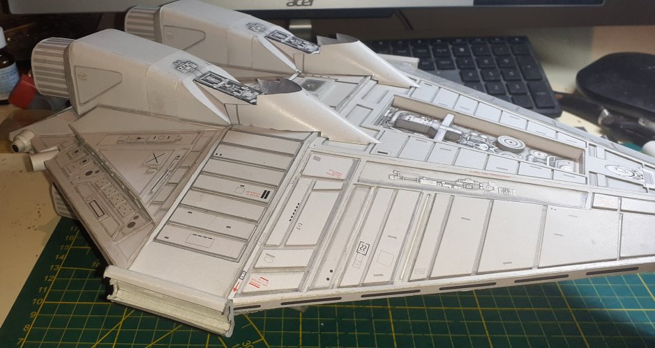
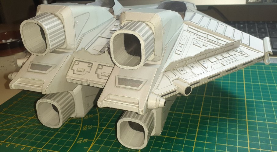
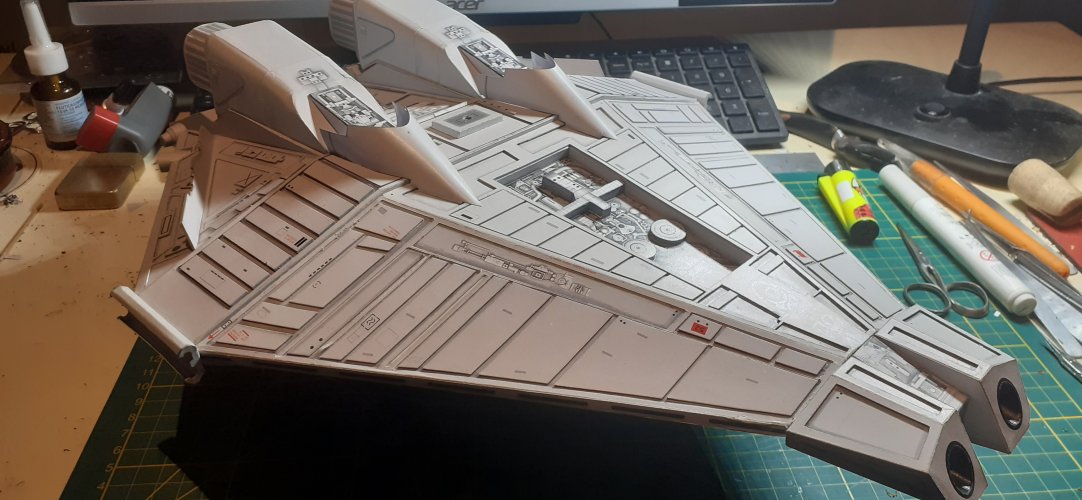
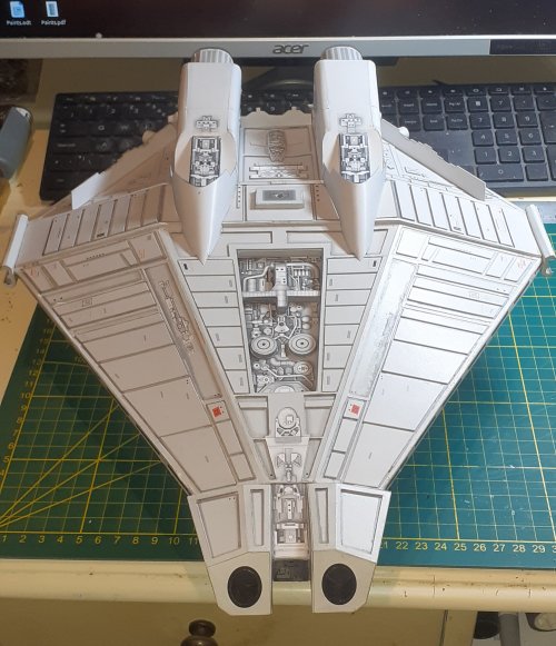
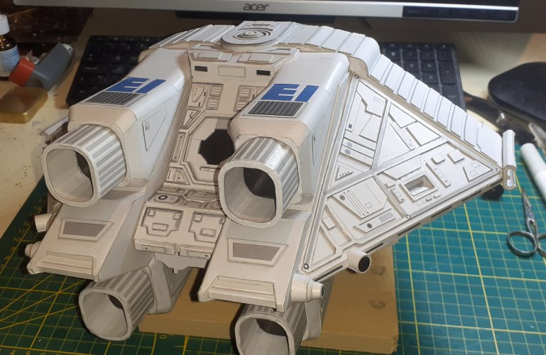
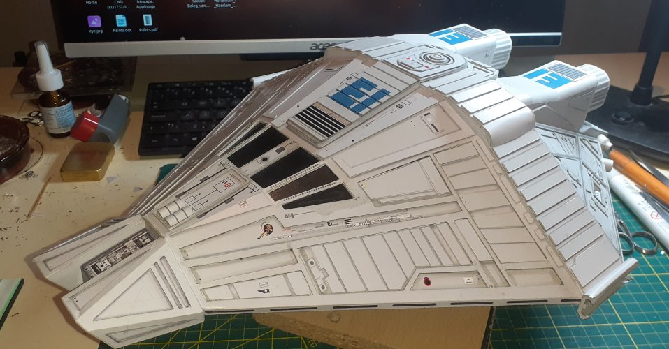
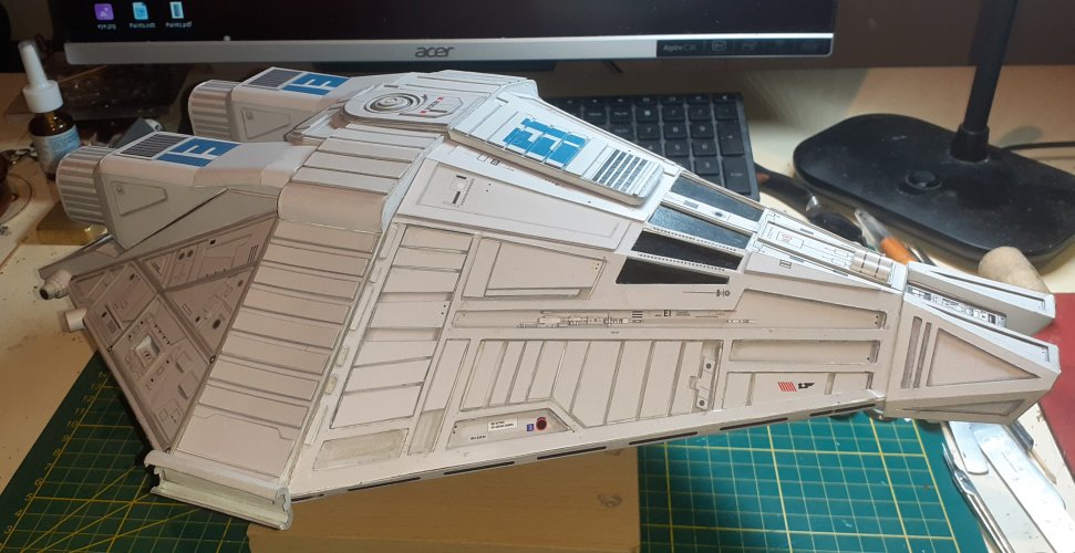
The completed engines are ready for mounting to the hull!!
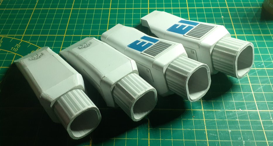
I am glad they are done! Very fiddly and a little frustrating at times, due to all the complex curves and angles.
They are not brilliant, but they came out ok, I think
See you all soon!!

With the bottom engines basically complete, I started on the top engines.
The top engines are a little more complex and the build procedure is different.
One thing to note here, when cutting out the floor of the engine, the part to the right in the pics below, be aware that the edge of the part under the indent has two angled planes and is not a straight cut. It is easy to miss this and if you do, it will create problems with alignment.
The main panels were cut out, edge coloured and pre-shaped..


In a similar fashion to the bottom engines, I back-tabbed the parts where necessary.
The exhaust cowling was made up first. When fitting the exhaust mounting plate make sure it is sitting perfectly square to all faces of the engine.


The main top panel was added next. I made up the grill detail panel and attached it to the main panel while I still had access, to glue it down firmly.

I made up the triangular side detail panels for the bottom and top engines.
The detail panels on the top engines are smaller than the bottom engines.
There is a fault in the template for these parts. The detail pieces that fit onto the small square of the side panel are not correct for the lower engines. They are too small!! The designer obviously copied the detail pieces from the top engines, but did not scale them up to fit the larger side panels of the bottom engines.
So, I made some new detail parts from spare card that fit correctly.

At this stage, I stopped adding panels and fitted the engine nozzles to the top and bottom engines. The reason for this, better access for gluing.


The front of the bottom engines was closed up, again making sure everything is nice and square with no twists.
The remaining panels for the top engines were carefully added, checking for squareness continuously.
The completed engines are ready for mounting to the hull!!

I am glad they are done! Very fiddly and a little frustrating at times, due to all the complex curves and angles.
They are not brilliant, but they came out ok, I think
See you all soon!!


