Working Signal Bridges using Tri-color LED

F

Fred_M

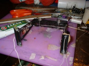
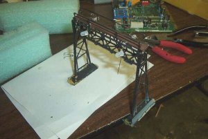
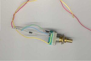
A simple to build and operate signal bridge can be made from a common HO signal bridge and a tri-colored LED. The LEDs we want are bipolar (two wire) red/green, yellow on AC type. I purchase them from www.allelectronics.com along with two 3 pole rotary switch, four 1N4001 diodes, and two 220 ohm ¼ watt limit resistors. I also use a 8 volt AC wall pack transformer (wall wart). Also needed are 4 #6 flat washers, .020 K&S brass rod, a soda straw, some fine stranded wire, and paint. We will need for tools a soldering iron with flux and solder, some CA gel, a 1/16 drill bit, clear silicon RTV, cutters, and needle nose pliers. Below is a list of electronic parts from one source. Feel free to get them from anywhere you want.

LEDs: http://www.allelectronics.com/cgi-bin/category.cgi?category=340080&item=LED-6&type=store

Wall Wart: http://www.allelectronics.com/matrix/AC_Wall_Transformers.html

Switch, rotary: http://www.allelectronics.com/cgi-bin/category.cgi?category=700425&item=RS-95&type=store

Diodes: http://www.allelectronics.com/cgi-bin/category.cgi?category=205100&item=1N4001&type=store


Resistors: http://www.allelectronics.com/matrix/One_Quarter_W_Resistors.html
 

Attachments

  • s1.jpg
    s1.jpg
    38.8 KB · Views: 139
F

Fred_M

First we remove the fake signal housings and put them in the junkyard. Same with the brackets. Next we bend the LEDs like in the picture. A note on this, one leg is longer than the other on LEDs for polarity. To save time and materials I wire the lights so that when one way is red the other is green (for each track). They are both yellow at the same time. You can wire them all separate but will need 4 switches, 8 diodes, and four 470 ohm limit resistors for each bridge. So on one side of the bridge the short leg goes up and on the other the long leg goes up. Next drill a 1/16 hole next to all four legs in the base. Bend two rod so they will go through the holes and bend around to follow the walkway. Mark where the LEDs need soldered and go to the next step.
 

Attachments

  • s2.jpg
    s2.jpg
    7.6 KB · Views: 139
F

Fred_M

Solder and trim the LEDS to the brass rods on the marks you made. One rod has the short side up and the other the short side down. These will be the “common” wires.
 

Attachments

  • s3.jpg
    s3.jpg
    31.1 KB · Views: 130
F

Fred_M

Thread the assemblies into the bridge and start securing them from the ground up with CA gel giving it plenty of time to set up. Bend as necessary.
 

Attachments

  • s4.jpg
    s4.jpg
    26.7 KB · Views: 129
F

Fred_M

This how you wire the rotary switches if you use the ones I do. Notice the diodes are reversed from each other, the center will supply AC. The yellow will be the input from the AC transformer. FRED
 

Attachments

  • switch.jpg
    switch.jpg
    9.5 KB · Views: 125
F

Fred_M

So then you bend the other Led legs over and CA and solder them to a wire, Each pair shares a wire. The brass commons can be combined in the hollow of the leg and soldered. Then I glue two flat washers onto the LEDs and go to bed. The best glue I found for this is automotive RTV clear. It sticks to the metal well. In the morning I will glue the other two on. Gravity is my clamps :rolleyes: FRED
 

Attachments

  • signal5.jpg
    signal5.jpg
    52.2 KB · Views: 116
F

Fred_M

Last step, tape off the LEDs and spay paint. Then cut a soda straw at a 45 degrre angle and glue them over the LEDs for sun hoods. Paint the hood with black craft paint and weather to taste. Plant and wire them . DONE. FRED
 

Attachments

  • s6.jpg
    s6.jpg
    38.5 KB · Views: 99
F

Fred_M

Ralph said:
That's terrific Fred! Thanks for following up your project with this helpful tutorial!
Ralph
Dedicated to My Friend Ralph. If you have any ?s feel free to ask. FRED