With a friend like me, my buddy needs....

doctorwayne

Active Member
Sep 6, 2005
3,516
0
36
Canada, eh?
an electrician.​


Sorry about the crummy drawing, but without a camera it's kind of difficult to explain the situation in order to pose a question. (Please ignore the "dots" at the left side of the diagram: it was the only way I could think of to keep the rest of the diagram from shifting to the left when this is posted.​


..M____a___________________________________________b_________N​
,............X................................................................X​
.............c.X_____________________________________X
..................X
.....................X_______________________D

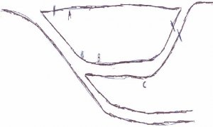
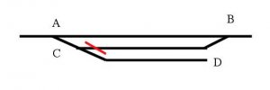
Line "M" - "N" is part of a main line (a complete loop around the room), with power feeds at M and N. All turnouts are Peco power routing type. With the turnouts at "a" and "b" aligned for the main, there is no power on the passing siding a-c-b or on the spur c-D. When either turnout "a" or "b" is aligned for the passing siding, along with "c", the passing siding is powered. The spur, c-D remains dead. So far, so good. However, with turnout "b" aligned for the main, and turnouts "a" and "c" aligned for the spur c-D, the passing track remains energized. I understand why this is so (the near rail of the passing siding is powered through switch "b", and the far rail is powered through switches "a" and "c"). (Spur c-D becomes energized as it should). To be able to keep a locomotive parked on the passing siding while another loco switches the spur, where do I need to cut the gap(s)? Since this is on the layout of a friend that I'm supposed to be helping, I'm reluctant to start hacking away without a few second opinions. Comments, please?


Wayne
 

Gary Pfeil

Active Member
May 7, 2001
2,510
0
36
Boonton NJ
Visit site
I'll take a swing at this. As I recall the basic rule for gapping power routing turnouts is you need a gap in every rail that joins the frog side of two turnouts. So, you need gaps in the rails I've marked A,B and C. Anywhere along their length is ok electrically, operationally you want to put them where it suits you desired operation. I'm not sure why my scan of my quick drawing cut off the top and bottom, I scanned twice with same result, but you can see enough to know what I'm referring to. Assuming the two turnouts on the main can be thrown independantly of each other, rails A and B need gaps, or there will be a short when one is thrown and the other is not. Having one control throw both may elimainate the need for gaps, but if they don't throw at precisely the same time, you will have a short. And being able to thow independantly is desireable. Where you put those gaps is up to you, I think I would gap A at the left side frog, and B at the other end. C would also be at the right hand side. This allows the turnout on the main leading to the stub to control the thru siding and the stub, by the way the two turnouts on that side are thrown. Either the thru siding or the stub will be powered. The main between the two mainline turnouts will only be powered by the turnout at right.
 

Attachments

  • drawing2.jpg
    drawing2.jpg
    27.3 KB · Views: 36

MasonJar

It's not rocket surgery
Oct 31, 2002
5,362
0
36
Ottawa, Canada
Visit site
I'm going to give it a try too...

If you put a gap in both rails just to the right of "C", it turns "C" into an off-on for track C-D. Turnout "B" controls the power for track B-C. With "A" and "B" set for track B-C, you effectively turn off track A-B as well.

Have I got that right? Running with DCC gives you the bonus of all track on, all the time...

Andrew
 

Attachments

  • wayne.jpg
    wayne.jpg
    24.6 KB · Views: 34

doctorwayne

Active Member
Sep 6, 2005
3,516
0
36
Canada, eh?
Thanks to all for the attempts to solve this dilemma. Perhaps my terminology was incorrect: when I said that the Peco turnouts were "power-routing", I meant that when they are lined for a track that does not have a separate source of power, the track becomes energized. When the turnout is not lined for this type of track, the track is dead. In the diagram, track M - N is always powered (there is also a separate feed, not shown, to this track between turnouts "a" and "b"). When "a" and "b" are lined for the main M - N, all other tracks are dead. Lining either turnout "a" or "b" for the passing siding will energize this track, and since there could be a train on this track that needs to leave from either end, its appropriate that either turnout be able to furnish power as required. The spur, from turnout "c" to point "D", is not energized unless turnout "c" is lined to the spur and also either turnout "a" or "b" also lined to the passing siding, thereby routing power to turnout "c". All of the tracks function as required when the proper turnouts are appropriately lined, with the exception that the spur "c" - "D" cannot be energized without inadvertently also energizing the passing track "c" - "b".
Let's say that we have a locomotive and train, headed East (to the left) parked in the passing siding. Parked on the spur is a helper locomotive, waiting for another eastbound train to arrive on the main line. As long as turnouts "a" and "b" are lined for the main, both the train on the passing track and the helper on the spur receive no power. When the eastbound train that will require the head-end helper (now sitting dead on the spur) arrives, the operator, by means of a switch on the control panel, cuts the power on the main line between turnouts "a" and "b", effectively freezing the newly arrived train just to the west of turnout "a". Next, turnout "a" is lined away from the main and turnout "c" is aligned to the spur "c" - "D". This energizes the spur, and the helper locomotive moves towards the mainline. Unfortunately, for some strange reason, the train on the passing track also begins to move at the same time, resu;lting in a collision somewhere in the vicinity of turnout "c". In essence, the spur "c" - "D" cannot be energized without also energizing the passing track "c" - "b".
I can do what I need by installing switches on a control panel and cutting the appropriate gaps: however, one of the main reasons my friend went with the Peco switches was for their power routing capabilities. As I mentioned in my original question, I can see why this happens, I just can't see how to overcome it while still fulfilling the requirement that an operator be able to use either turnout "a" or "b" to energize the passing siding.

Wayne
 

Gary Pfeil

Active Member
May 7, 2001
2,510
0
36
Boonton NJ
Visit site
OK Wayne. You already have the gaps on the main. I don't see any way to use the turnouts to control the thru siding from both ends, as both rails are powered by the non-frog side of the turnouts at either end, which as you say you already understand. In my drawing I show a gap in what I labelled rail c. This will do what you wnat, at the expense of having to have turnout c aligned for that route. Where you place that gap on that rail depends on what the typical operation is. For instance, if the most common use is for trains entering from the right and turnout c is kept thrown for the stub, or turnout a for the main, when turnout b is thrown for the thru siding, it will be powered up to the gap. Depending on the length of the siding and the length of the trains using it, position the gap to allow entry to clear the main, if possible, then place the gap. Any additional length on the siding will be powered from the left. Or, do the opposite, as I show in the drawing. Bottom line is you can have it in one direction. For the other direction, you would need to have the appropriate turnout(s) thrown on the other end. As you mentioned, gaps at each end and a block switch gives you the most flexibility. Power routing turnouts are most useful for stub tracks.

As Andrew said, DCC...

Gary
 

doctorwayne

Active Member
Sep 6, 2005
3,516
0
36
Canada, eh?
Thanks Gary, I think that your observation about this type of turnout being best for stub tracks is true. I imagine that this area will probably merit its own control panel, as the diagram shows only a small portion of the tracks that will eventually be in service here. The stub siding will soon become a turntable lead to the right, with other trackage running left to a diesel shop. The area between the present stub siding and the passing track is slated to become a steam loco servicing facility, with a three track coaling tower, ash hoist, and water columns, along with a ready track.
I also agree with both you and Andrew about DCC solving all of the problems that this area will pose. It would also go a long way to solving any financial problems my own railroad might have, since the job of installing decoders in the close to one hundred locos that my friend, Ed, has in service would most likely fall to me. However, his primary interest, after collecting, is solo operation of a single track main line. Besides that, DCC in his locos would mean no more running rights on each other's layouts and no more test runs on my layout of all the locomotives that I've worked on for him: right now, I've got a really nice little brass CNR H-6-d that I borrowed from him to use as a pattern to make my own versions from a pair of Bachmann 4-6-0's. Unfortunately, in my opinion, the diameter of the Bachmann boiler is a little too small, not a big deal in itself, but coupled with the need to change the spacing of the rear drivers, more than I care to do. I temporarily considered using the two to make NYC F-82's #880 and #881 (1936 numbers, probably better known to most as #1290 and #1291, running out of St. Thomas, Ontario): except for the domes and the air pump, dead ringers for the Bachmann loco. However, the cost of four suitable tenders, all of which would require extensive modifications, compounded by the fact that there's no suitable place to include a NYC interchange on my layout has left me with no choice but to modify them for service on my own Grand Valley. I've already rebuilt the slide valves into piston valves, (actually a pretty simple job) and plan on building new cabs and generally updating them, based loosely on the appearance of the CNR loco, with more than a passing nod to standard practices on the GVC.
As you can probably tell from this rambling discourse, electrical stuff only grabs my interest if it impinges on the trains themselves. As a matter of fact, Ed might have been content to be only a collector until he had been out here a few times to run his trains. As his chief mechanical officer, it's my job to get his layout running: I view it as an added bonus to a great friendship.
Once again, guys, thanks for your input. By the way, Ed has agreed to let me post pictures as I convert his Akane USRA 2-10-2 into a CNR T-3-a. We're just waiting for parts, so stay tuned.

Wayne
 

60103

Pooh Bah
Mar 25, 2002
4,754
0
36
Brampton, Ontario, Canada
Visit site
Wayne:
are the turnouts powered or manual? If they're powered with switch machines with extra contacts, I propose the following: Isolate all the sidings and spurs and the main line at the frog end of the switch and at the points end of the switches at M and N.
Put in on/off switches for each track. Wire each turnout from the two tracks it's connected to using the switch machine to choose which one powers it. At the complicated end, you would have to wire the series of turnouts. Then the switches would pick up power from the track they're connected to.
If you have cab control, you'll need a cab selector as well.
 

doctorwayne

Active Member
Sep 6, 2005
3,516
0
36
Canada, eh?
Thanks, David, for your reply. Your suggestion would work well, except for the fact that the turnouts are literally manually controlled: big finger, deftly wielded between point rails, moves points. I think we'll probably go with a separate control panel. When I get stuck, the layout's done!!
Seriously though, while I'm pretty capable painting or modifying cars and locos, wiring a train layout is one of my many weak areas. And this is from a guy who built and wired his own house.
Wayne
 

MasonJar

It's not rocket surgery
Oct 31, 2002
5,362
0
36
Ottawa, Canada
Visit site
If A-B is powered all the time, and all you want to do is control power to B-C, then you need to put a gap at one end of B-C or the other... A gap where I marked it means that turnout B controls the power, and a gap at the opposite end effectively gives turnout A control.

Andrew