

Willys Jeep from Modelik
- Thread starter lriera
- Start date
You are using an out of date browser. It may not display this or other websites correctly.
You should upgrade or use an alternative browser.
You should upgrade or use an alternative browser.
- Status
- Not open for further replies.
Hello companions,
Here I am with the engine and that is a very difficult part. The engine is by itself almost a complete model. But in addition one very complicated that has put my patience on approval. Nevertheless, with many difficulties and problems, but I believe that in the end I am being able to solve them. Although for another occasion, I will have learned many things that are going to be very useful to me.
And now we go on the commentary of the photos, that these time are many.
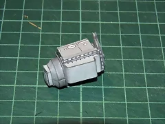
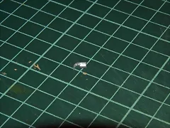
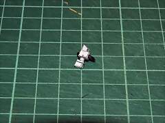
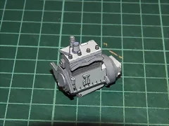
In Photo 180 you can see the pieces that comprise front and back of the engine. Those that communicate the ventilation of the radiator and the box of transmission reduction. In Photo 181 I have stuck the piece that will form the transmission of the refrigeration of the radiator and in Photos 182 and 183 I have stuck the piece that is united to the box of transmission and the crankcase.
180. 181.
181.
 182.
182.
 183.
183.
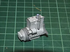
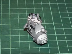
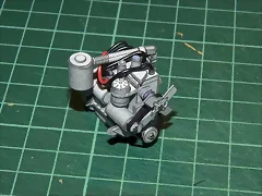
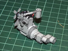
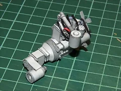
Photos 184, 185 and 186 are different views of the engine at this stage of the work.
184. 185.
185.
 186.
186.
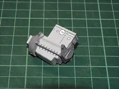
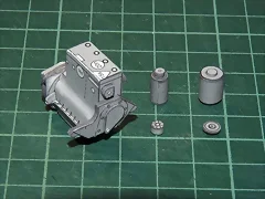
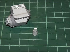
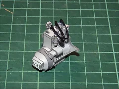
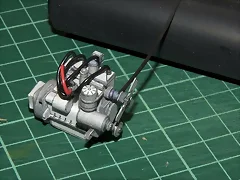
Photo 187 shows how I have made the holes that will lodge the different pieces that will form the ventilation of the radiator. And in the Photo 188 different pieces already made. The carburetor top at the right, to its side I imagine that it is the dynamo and underneath the connector of spark plugs and one of the discs that the fan belt will cross.
187. 188.
188.
In Photos 189, 190, 191 and 192 different phases from the assembly of the piece than must represent the electrical engine of diesel engine start-up.
189. 190.
190.
 191.
191.
 192.
192.
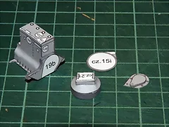
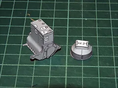
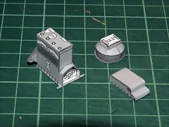
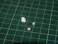
In Photos 193, 194, 195, 196, 197, 198 and 199 also you can see different phases from assembly of the piece that connects the carburetor with the cylinders. The two square boxes and the triangular box, although I do not show it here, are stuffed of squared card pieces, because there was no way to obtain that the boxes had the square form. I even filled up the angled one with different card pieces that had the triangular form. And some views of the finished piece (198 and 199).
193. 194.
194.
 195.
195.

196. 197.
197.
 198.
198.
 199.
199.

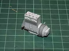
In Photo 200 a view of the engine with the different pieces that I have beaten until this moment to the body.
200.
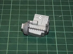
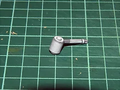
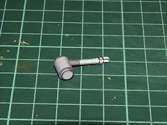
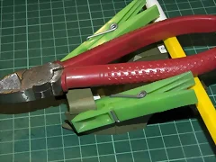
And finally, in Photo 201 you can see how I use the tweezers to hold the pieces that form the carburetor and in the Photos 202 and 203 two views of this last one already finished.
201. 202.
202.
 203.
203.
Well, this is everything at the moment, and it’s not little. Now I already face the final straight line of the engine. I hope to finish it in some days. I will maintain informed you about the progresses.
Greetings.
Here I am with the engine and that is a very difficult part. The engine is by itself almost a complete model. But in addition one very complicated that has put my patience on approval. Nevertheless, with many difficulties and problems, but I believe that in the end I am being able to solve them. Although for another occasion, I will have learned many things that are going to be very useful to me.
And now we go on the commentary of the photos, that these time are many.
In Photo 180 you can see the pieces that comprise front and back of the engine. Those that communicate the ventilation of the radiator and the box of transmission reduction. In Photo 181 I have stuck the piece that will form the transmission of the refrigeration of the radiator and in Photos 182 and 183 I have stuck the piece that is united to the box of transmission and the crankcase.
180.
181.
182.
183.
Photos 184, 185 and 186 are different views of the engine at this stage of the work.
184.
185.
186.
Photo 187 shows how I have made the holes that will lodge the different pieces that will form the ventilation of the radiator. And in the Photo 188 different pieces already made. The carburetor top at the right, to its side I imagine that it is the dynamo and underneath the connector of spark plugs and one of the discs that the fan belt will cross.
187.
188.
In Photos 189, 190, 191 and 192 different phases from the assembly of the piece than must represent the electrical engine of diesel engine start-up.
189.
190.
191.
192.
In Photos 193, 194, 195, 196, 197, 198 and 199 also you can see different phases from assembly of the piece that connects the carburetor with the cylinders. The two square boxes and the triangular box, although I do not show it here, are stuffed of squared card pieces, because there was no way to obtain that the boxes had the square form. I even filled up the angled one with different card pieces that had the triangular form. And some views of the finished piece (198 and 199).
193.
194.
195.
196.
197.
198.
199.
In Photo 200 a view of the engine with the different pieces that I have beaten until this moment to the body.
200.
And finally, in Photo 201 you can see how I use the tweezers to hold the pieces that form the carburetor and in the Photos 202 and 203 two views of this last one already finished.
201.
202.
203.
Well, this is everything at the moment, and it’s not little. Now I already face the final straight line of the engine. I hope to finish it in some days. I will maintain informed you about the progresses.
Greetings.
Hi to everybody,
And now new advances on the engine, but this time it is a very important one, because I only have left to place the carburetor and the ventilator of the radiator and its strap.
In this occasion I have placed the connections that go until the spark plugs. They are cables and there I have complicated my life excessively, because it wanted to use electrical thread, yes or yes, and it had far better gone to me to use any other material simpler to handle. The result at view, is that the cables are too heavy, nevertheless for me has been a lesson of many techniques and patience.
Between the techniques there is the one to harden pieces of paper with cyanocrilate. I had read about this technique in some Forums, but I had never proven it. And I think it works very well. Although it is necessary to go with care, because this glue beats even the skin and in addition it smells very bad.
But enough with the introduction and we happen to comment the session of photographies.
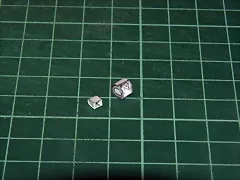
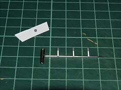
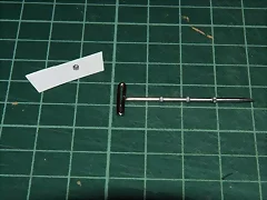
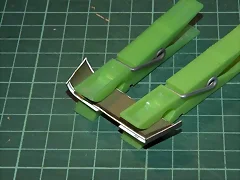
In Photo 204 you can see the hoops that simulate the connections of electrical cables to the body of the engine. On the paper is already a hoop finished and passed through cyano, and in the pin beaten with the usual glue, the three remaining pieces. In Photo 205 I already have coiled and stuck the three pieces on the pin. And in Photo 206 I am giving them the bath on cyano to harden them. The reason for it is because it seemed to me that if these pieces were not really hard, when I stuck the cables, they were going to deform.
204. 205.
205.
 206.
206.
In Photo 207 I already have stuck the four pieces to the superior part of the engine. You can observe while, that in successive photographies, I am sticking some new pieces to the engine body. In Photo 208 I also have made the five pieces that go on the dynamo, all also hardened with cyano.
207. 208.
208.

And in photos 209, 210, 211, 212 and 213 you can see how I have been placing five cables in its respective lodgings. The truth is that now I would not return to do it in this form, but as I said to you it has served to me to practice new techniques, to use new materials and, mainly, to take much patience, because I assure to you that it was not far from easy to obtain that the cables stayed at their place.
209. 210.
210.
 211.
211.
212. 213.
213.
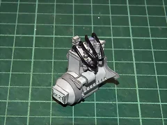
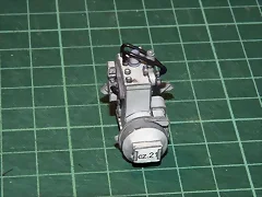
Finally, in Photos 214 and 215 you can see two views of the engine at the end of these works, with all the cables in its place.
214. 215.
215.
Well that is everything at the moment, we will see if now I begin to take a little more speed on the build.
Until very soon.
Greetings to all.
And now new advances on the engine, but this time it is a very important one, because I only have left to place the carburetor and the ventilator of the radiator and its strap.
In this occasion I have placed the connections that go until the spark plugs. They are cables and there I have complicated my life excessively, because it wanted to use electrical thread, yes or yes, and it had far better gone to me to use any other material simpler to handle. The result at view, is that the cables are too heavy, nevertheless for me has been a lesson of many techniques and patience.
Between the techniques there is the one to harden pieces of paper with cyanocrilate. I had read about this technique in some Forums, but I had never proven it. And I think it works very well. Although it is necessary to go with care, because this glue beats even the skin and in addition it smells very bad.
But enough with the introduction and we happen to comment the session of photographies.
In Photo 204 you can see the hoops that simulate the connections of electrical cables to the body of the engine. On the paper is already a hoop finished and passed through cyano, and in the pin beaten with the usual glue, the three remaining pieces. In Photo 205 I already have coiled and stuck the three pieces on the pin. And in Photo 206 I am giving them the bath on cyano to harden them. The reason for it is because it seemed to me that if these pieces were not really hard, when I stuck the cables, they were going to deform.
204.
205.
206.
In Photo 207 I already have stuck the four pieces to the superior part of the engine. You can observe while, that in successive photographies, I am sticking some new pieces to the engine body. In Photo 208 I also have made the five pieces that go on the dynamo, all also hardened with cyano.
207.
208.
And in photos 209, 210, 211, 212 and 213 you can see how I have been placing five cables in its respective lodgings. The truth is that now I would not return to do it in this form, but as I said to you it has served to me to practice new techniques, to use new materials and, mainly, to take much patience, because I assure to you that it was not far from easy to obtain that the cables stayed at their place.
209.
210.
211.
212.
213.
Finally, in Photos 214 and 215 you can see two views of the engine at the end of these works, with all the cables in its place.
214.
215.
Well that is everything at the moment, we will see if now I begin to take a little more speed on the build.
Until very soon.
Greetings to all.
Hello companions,
And finally… I have finished the engine. Already it was time! Because it has been difficult to me.
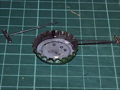
Next I tell you how they have been the last steps. In Photo 216 I have already placed the ventilator of the radiator. As axis I have used a needle of those of seam that I have trimmed. In Photo 217 I have stuck the dynamo and in Photo 218 I have stuck the last inferior wheel and I am sticking the strap that unites all. As always, step by step the pieces stick better. I began by above and I went sticking the strap to each wheel, one behind another one, hoping to that each was dried. In Photo 219 you can see the strap and the wheels already placed.
216. 217.
217.
 218.
218.
 219.
219.
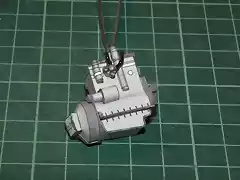
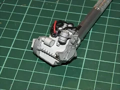
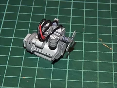
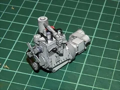
Finally, in Photos 220, 221, 222 and 223, shows the finished engine with all the stuck elements, including the carburetor and the reducing box, from four different angles.
220. 221.
221.
 222.
222.
 223.
223.
Well, that is everything so far. I do not know if what comes is going to be as laborious as this that I have finished. I believe that no, and so I hope that I can accelerate the construction of the Willys. Although one is in a hobby, I am in a hurry to begin some new model.
Greetings to all and until soon.
And finally… I have finished the engine. Already it was time! Because it has been difficult to me.
Next I tell you how they have been the last steps. In Photo 216 I have already placed the ventilator of the radiator. As axis I have used a needle of those of seam that I have trimmed. In Photo 217 I have stuck the dynamo and in Photo 218 I have stuck the last inferior wheel and I am sticking the strap that unites all. As always, step by step the pieces stick better. I began by above and I went sticking the strap to each wheel, one behind another one, hoping to that each was dried. In Photo 219 you can see the strap and the wheels already placed.
216.
217.
218.
219.
Finally, in Photos 220, 221, 222 and 223, shows the finished engine with all the stuck elements, including the carburetor and the reducing box, from four different angles.
220.
221.
222.
223.
Well, that is everything so far. I do not know if what comes is going to be as laborious as this that I have finished. I believe that no, and so I hope that I can accelerate the construction of the Willys. Although one is in a hobby, I am in a hurry to begin some new model.
Greetings to all and until soon.
Hi buddies,
Now with the body. It has taken a little more than I thought, because this part is not as entertained as the engine, but it also has many pieces.
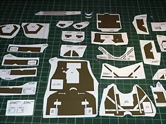
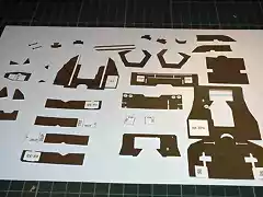
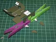
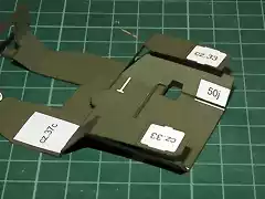
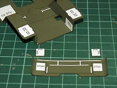
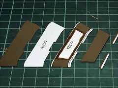
In Photo 224 you can see a part of the pieces that compose the frame of the body, cut coarsely and, those that needed it, beaten to cardboards of the corresponding thicknesses. It is necessary to fold other pieces and stick them on themselves, like the numbered 27n, down to the right. In the Photo 225 the same pieces of the Photo 224, but all cut to its respective sizes and ready for the assembly. I have done also the cleaved (I don’t know if the correct word is cleaved or scored, but you understand what I mean, right?) in the pieces that needed it, before cutting them.
224. 225.
225.
In Photo 226 I have begun to stick the pieces that form the inferior frame of the body. And in Photo 227 I have stuck the frame to the base of the body. You may see that before sticking the pieces, I have folded all them. During the patch many of them lose the form, but as they already have the cleaved, it does not take as much that they take the final form.
226. 227.
227.

In Photo 228 I am sticking the frontal part of the frame and in Photos 229 and 230, I am sticking the pieces that comprise that frontal part, with its vertical reinforcements.
228. 229.
229.
 230.
230.
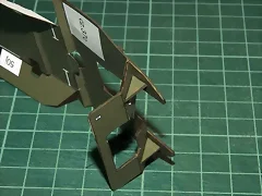
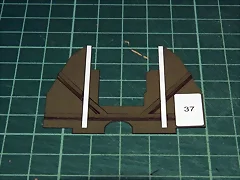
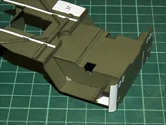
In Photo 231 I am sticking the lateral interiors of the body and already there, I am preparing the “wings” than will be the mudguard. You observe that, as always, I stick the pieces little by little, so that it is easier to me, on the one hand, to align them, and on the other, to fold them so that they take the final form. And in Photo 232, I am sticking the inferior back part of the frame. Also I come step by step. In this case I have stuck the part of the bottom before the fold, and soon, I will stick the folded and the final part of this piece, the one that is more down in the Photo.
231. 232.
232.

Tomorrow, I hope, I will follow with the assembly of the body.
Until then, greetings to all.
Now with the body. It has taken a little more than I thought, because this part is not as entertained as the engine, but it also has many pieces.
In Photo 224 you can see a part of the pieces that compose the frame of the body, cut coarsely and, those that needed it, beaten to cardboards of the corresponding thicknesses. It is necessary to fold other pieces and stick them on themselves, like the numbered 27n, down to the right. In the Photo 225 the same pieces of the Photo 224, but all cut to its respective sizes and ready for the assembly. I have done also the cleaved (I don’t know if the correct word is cleaved or scored, but you understand what I mean, right?) in the pieces that needed it, before cutting them.
224.
225.
In Photo 226 I have begun to stick the pieces that form the inferior frame of the body. And in Photo 227 I have stuck the frame to the base of the body. You may see that before sticking the pieces, I have folded all them. During the patch many of them lose the form, but as they already have the cleaved, it does not take as much that they take the final form.
226.
227.
In Photo 228 I am sticking the frontal part of the frame and in Photos 229 and 230, I am sticking the pieces that comprise that frontal part, with its vertical reinforcements.
228.
229.
230.
In Photo 231 I am sticking the lateral interiors of the body and already there, I am preparing the “wings” than will be the mudguard. You observe that, as always, I stick the pieces little by little, so that it is easier to me, on the one hand, to align them, and on the other, to fold them so that they take the final form. And in Photo 232, I am sticking the inferior back part of the frame. Also I come step by step. In this case I have stuck the part of the bottom before the fold, and soon, I will stick the folded and the final part of this piece, the one that is more down in the Photo.
231.
232.
Tomorrow, I hope, I will follow with the assembly of the body.
Until then, greetings to all.
Hello companions,
Today I bring new advances at the Willys.
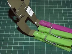
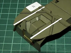
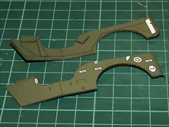
In Photo 233 I am sticking the two “wings” that will be the superior part of the mudguard of the Jeep. As always, I will not get tired to repeat it, it is better to come step by step. Thus, with these pieces I have begun sticking the tongue-piece inferior to the relief that, in that zone, has the ground of the chassis. As you see, the other parts of the two pieces are still “on the air”. Once dry, I have continued sticking the other parts, as you can see in Photo 234.
233. 234.
234.

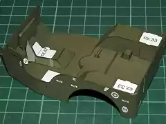
In Photo 235 I am preparing the piece that constitutes the back part of the Willys, with its reinforcements. In Photo 236 I have already stuck that piece and both reinforcements, underneath the “wings” and to the laterals of the body.
235. 236.
236.

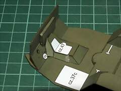
In Photo 237 I am sticking the piece that comprises the inferior part of the mudguard and in Photo 238 you can see already patch the small triangle that kills the edge of the mudguard, so that the passengers cannot hurt themselves.
237. 238.
238.

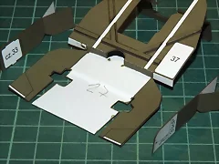
Photos 239 and 240 show how I have stuck the round piece that reinforces the ground of the chassis in the central part.
239. 240.
240.
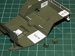
And Photos 241 and 242 shows bottom and top, the vertical piece that separate the passengers from the engine already stuck in its place and on the ground the horizontal piece that covers the gear box and transmission. This piece cost horrors to me. As the instructions are in Pole, I guide myself at the order of my assembly, by the photographies of companions of other forums. And at them it seemed to me to see that first it was necessary to mount the part of the ground soon and the vertical piece after. Serious mistake. Once glued I had to cut it out and to fit as I could the vertical. I hope that it is not so evident. I mention it in case somebody wants to mount this model, so that it does not encounter in the same problems that I.
241. 242.
242.
Well that is everything at the moment. The following thing will be to advance at the body. I believe that with those works, we will be able to have one better vision of the aspect of the model once finished.
Until the following post.
Greetings.
Today I bring new advances at the Willys.
In Photo 233 I am sticking the two “wings” that will be the superior part of the mudguard of the Jeep. As always, I will not get tired to repeat it, it is better to come step by step. Thus, with these pieces I have begun sticking the tongue-piece inferior to the relief that, in that zone, has the ground of the chassis. As you see, the other parts of the two pieces are still “on the air”. Once dry, I have continued sticking the other parts, as you can see in Photo 234.
233.
234.
In Photo 235 I am preparing the piece that constitutes the back part of the Willys, with its reinforcements. In Photo 236 I have already stuck that piece and both reinforcements, underneath the “wings” and to the laterals of the body.
235.
236.
In Photo 237 I am sticking the piece that comprises the inferior part of the mudguard and in Photo 238 you can see already patch the small triangle that kills the edge of the mudguard, so that the passengers cannot hurt themselves.
237.
238.
Photos 239 and 240 show how I have stuck the round piece that reinforces the ground of the chassis in the central part.
239.
240.
And Photos 241 and 242 shows bottom and top, the vertical piece that separate the passengers from the engine already stuck in its place and on the ground the horizontal piece that covers the gear box and transmission. This piece cost horrors to me. As the instructions are in Pole, I guide myself at the order of my assembly, by the photographies of companions of other forums. And at them it seemed to me to see that first it was necessary to mount the part of the ground soon and the vertical piece after. Serious mistake. Once glued I had to cut it out and to fit as I could the vertical. I hope that it is not so evident. I mention it in case somebody wants to mount this model, so that it does not encounter in the same problems that I.
241.
242.
Well that is everything at the moment. The following thing will be to advance at the body. I believe that with those works, we will be able to have one better vision of the aspect of the model once finished.
Until the following post.
Greetings.
Hello once again,
Today I bring a new advance at the Willis Jeep. This time is the auto body. In Photo 243 they appear, before cutting them, the pieces that are going to be the sidewalls and the part where the hood of the Willys will be fixed. And in the Photo 244 all those pieces already cut and prepared for the assembly.
243. 244.
244.

In Photos 245 and 246 they appear the pieces that cover the back shock absorbers in the Jeep, before their positioning and once stuck in its place.
245. 246.
246.

Photo 247 shows the two sidewalls of the body, to which already I have given form.
247.
In Photo 248 I am sticking the left wall. As always, first I stick the back part of the piece before the ply and soon I came to stick the fore part. In Photo 249 both lateral pieces are beaten.
248. 249.
249.

Photo 250 shows the pieces that compose the frontal part of the body where the hood is fixed to the body. In Photo 251 I am sticking them to each other. This piece turned out to be quite difficult to mount because the ends are doubled and it is necessary to do it with a lot of care. First it is necessary to double each piece of paper separately, and soon when uniting each one of the pieces, it is necessary to obtain that they stay doubled.
250. 251.
251.
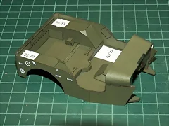
In Photo 252 I am sticking them to the body. And in Photo 253 you can see the finished body.
252. 253.
253.
Good, in a little time I will be able to mount all the pieces that I have been accumulating of the Willys. I can assure to you that the aspect is impressive, although I reserve myself the presentation, because before I must make other many small tasks, like for example glueing the axes of the wheels to the chassis, sticking the wheels to the axes, place the motor and the radiator in its place, mount the arms of transmission of the motor to the boxes of transmission, etc. As you see I have veeeery much ahead work.
Up to soon, with more progresses.
Greetings to all.
Today I bring a new advance at the Willis Jeep. This time is the auto body. In Photo 243 they appear, before cutting them, the pieces that are going to be the sidewalls and the part where the hood of the Willys will be fixed. And in the Photo 244 all those pieces already cut and prepared for the assembly.
243.
244.
In Photos 245 and 246 they appear the pieces that cover the back shock absorbers in the Jeep, before their positioning and once stuck in its place.
245.
246.
Photo 247 shows the two sidewalls of the body, to which already I have given form.
247.
In Photo 248 I am sticking the left wall. As always, first I stick the back part of the piece before the ply and soon I came to stick the fore part. In Photo 249 both lateral pieces are beaten.
248.
249.
Photo 250 shows the pieces that compose the frontal part of the body where the hood is fixed to the body. In Photo 251 I am sticking them to each other. This piece turned out to be quite difficult to mount because the ends are doubled and it is necessary to do it with a lot of care. First it is necessary to double each piece of paper separately, and soon when uniting each one of the pieces, it is necessary to obtain that they stay doubled.
250.
251.
In Photo 252 I am sticking them to the body. And in Photo 253 you can see the finished body.
252.
253.
Good, in a little time I will be able to mount all the pieces that I have been accumulating of the Willys. I can assure to you that the aspect is impressive, although I reserve myself the presentation, because before I must make other many small tasks, like for example glueing the axes of the wheels to the chassis, sticking the wheels to the axes, place the motor and the radiator in its place, mount the arms of transmission of the motor to the boxes of transmission, etc. As you see I have veeeery much ahead work.
Up to soon, with more progresses.
Greetings to all.
")
Fishcarver
Active Member

Hello companions,
I promised more and here I am. Now it is the turn to mount the buckets of the axes, to which the wheels, the direction and the arms of transmission of the gear box, fix to the axes of the wheels.
In the Photo 262 the pieces which I am going to fulfill this phase. You may observe the four pieces of previous post that, between all the others, almost get unnoticed (but the work that is there!).
262.
In Photo 263 I have stuck the three pieces that will form the direction. They are those that have so visible the white points. One is behind the frame and it is not seen.
263.
In Photo 264 I have stuck the box of gear of the steering wheel. Look that a straight piece of paper connects this box with the arms of the L of the direction, on the front axis.
264.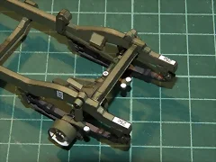
In Photo 265 I offer to you a general view of the frame until this moment. In it the buckets of fixation of the wheels are appraised. I had stuck these before, but the four are better seen here. The frame continues maintaining itself balanced perfectly, without no inclination, on the four crossbows and shock absorbers.
265.
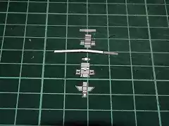
In Photo 266 I already have stuck the two rods of wire that connect the L of the direction with stringers that move the wheels. Look that on each end of the rods I have placed a piece of round paper. Of these pieces there were only two in kit, that’s why I have had to print several more until having one for each location.
266.
In Photo 267 I am sticking the radiator of the engine in its place on the frame. No problem here.
267.
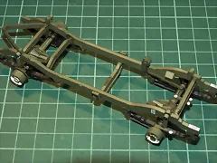
And finally in the sequence of Photos 268 to 271 I offer you a general view of the state of the Willys until this moment. This already begins to look like a vehicle! After so many weeks working, it seems that already I see something of light, not the one at the end of the tunnel, but at least, something of light. In these photographies you can see that I have also stuck the axes of communications of shaft thrust of the wheels, with the pieces that I have mentioned several times.
268.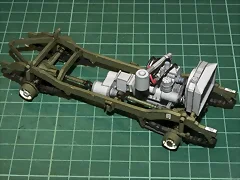 269.
269.
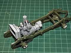 270.
270.
 271.
271.

Well, now it follows the body. I will keep you upgraded.
Until then, greetings to all.
I promised more and here I am. Now it is the turn to mount the buckets of the axes, to which the wheels, the direction and the arms of transmission of the gear box, fix to the axes of the wheels.
In the Photo 262 the pieces which I am going to fulfill this phase. You may observe the four pieces of previous post that, between all the others, almost get unnoticed (but the work that is there!).
262.
In Photo 263 I have stuck the three pieces that will form the direction. They are those that have so visible the white points. One is behind the frame and it is not seen.
263.
In Photo 264 I have stuck the box of gear of the steering wheel. Look that a straight piece of paper connects this box with the arms of the L of the direction, on the front axis.
264.
In Photo 265 I offer to you a general view of the frame until this moment. In it the buckets of fixation of the wheels are appraised. I had stuck these before, but the four are better seen here. The frame continues maintaining itself balanced perfectly, without no inclination, on the four crossbows and shock absorbers.
265.
In Photo 266 I already have stuck the two rods of wire that connect the L of the direction with stringers that move the wheels. Look that on each end of the rods I have placed a piece of round paper. Of these pieces there were only two in kit, that’s why I have had to print several more until having one for each location.
266.
In Photo 267 I am sticking the radiator of the engine in its place on the frame. No problem here.
267.
And finally in the sequence of Photos 268 to 271 I offer you a general view of the state of the Willys until this moment. This already begins to look like a vehicle! After so many weeks working, it seems that already I see something of light, not the one at the end of the tunnel, but at least, something of light. In these photographies you can see that I have also stuck the axes of communications of shaft thrust of the wheels, with the pieces that I have mentioned several times.
268.
269.
270.
271.
Well, now it follows the body. I will keep you upgraded.
Until then, greetings to all.
Fishcarver
Active Member
Logicman, Fishcarver thank you for your nice words. Now that I have begun the body, I feel that things will be quicker, I hope.
Lluis,
The frame and engine assembly looks great!. You're getting close to the finished model.
Ken
The frame and engine assembly looks great!. You're getting close to the finished model.
Ken
Lluis,
Your Jeep is looking great :thumb: It won't be long now, your entering the home streach. Any thoughts on you next project? Armor perhaps?
Kevin
Your Jeep is looking great :thumb: It won't be long now, your entering the home streach. Any thoughts on you next project? Armor perhaps?
Kevin
- Status
- Not open for further replies.