Voyager Spacecraft 1/24

jparenti

Member
Jun 3, 2006
54
0
16
41
Vienna, Illinois, USA
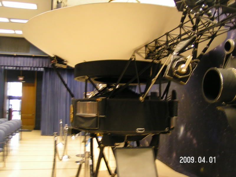
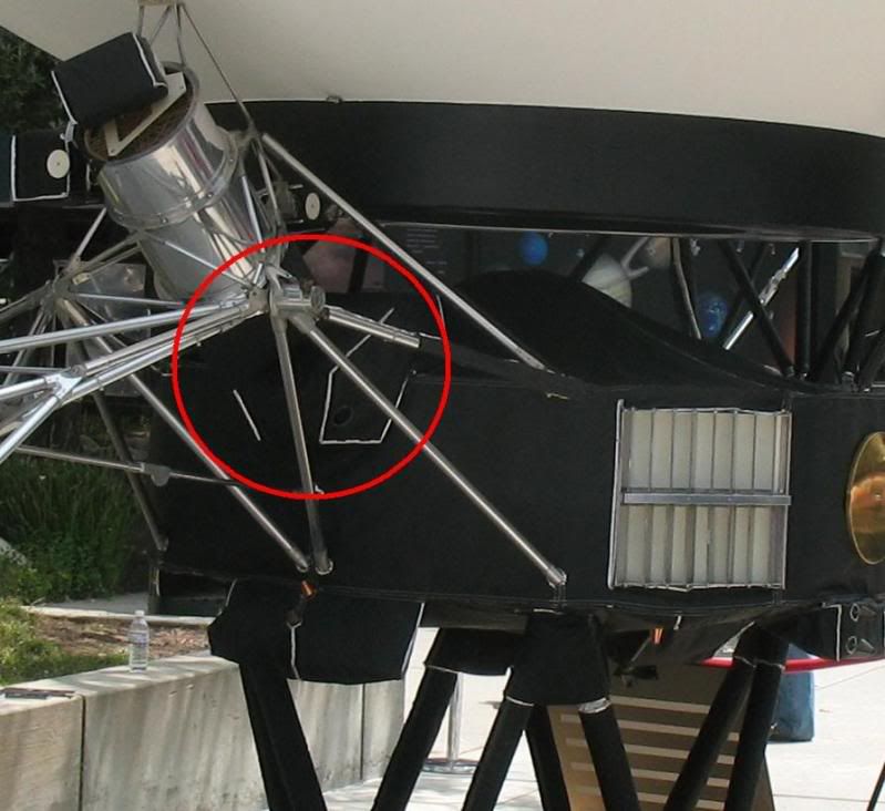
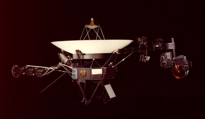
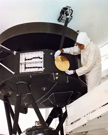
Hello all. Most everyone has probably seen Ton Noteboom's 1/24 scale Voyager spacecraft at jleslie's site, but so far I don't know if anyone else has built it. The actual spacecraft:

voyager2.jpg


I myself built one last summer, which turned out fine by my own standards, but I decided to try something new with it and add more detail.
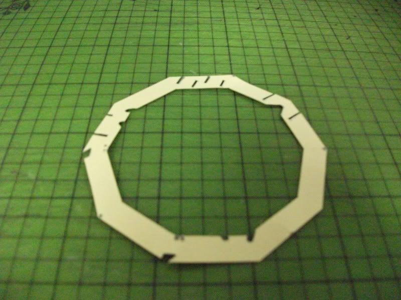
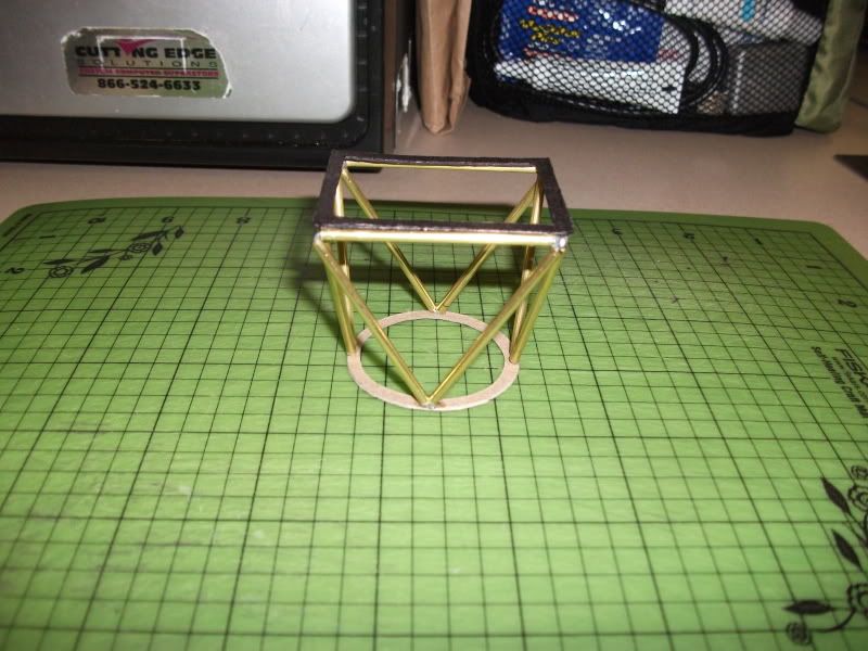
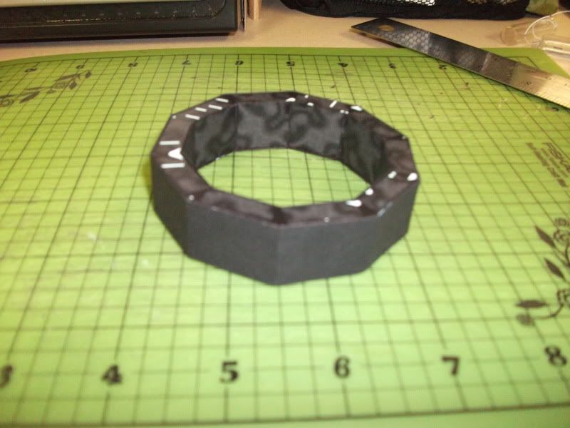
I started with the spacecraft bus.

DSCF0127.jpg


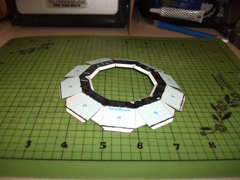
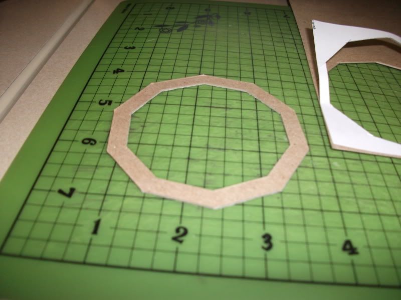
From my own experience, the bus can warp slightly after a time, so I bulked up the inside top and bottom with 1 mm card.

DSCF0129.jpg


DSCF0130.jpg


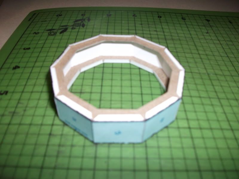
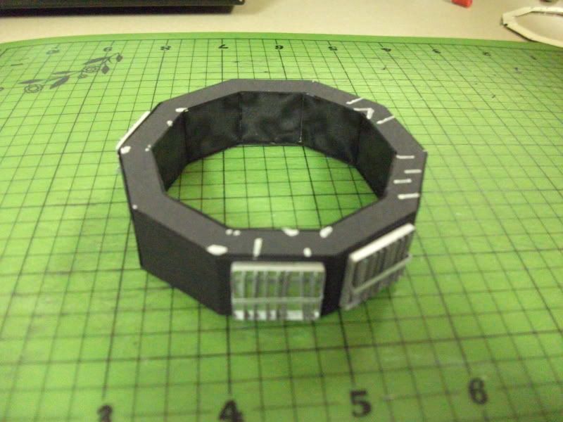
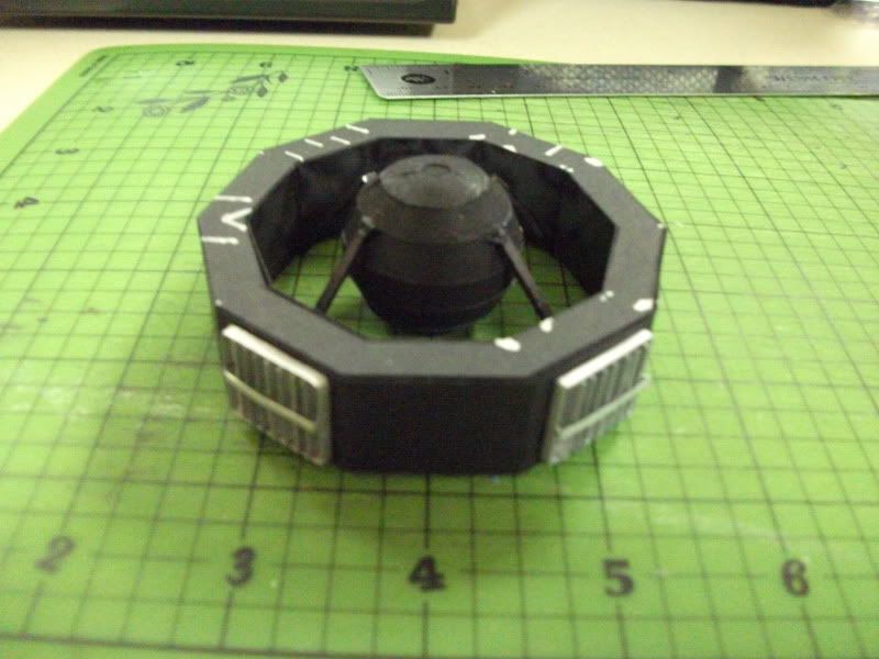
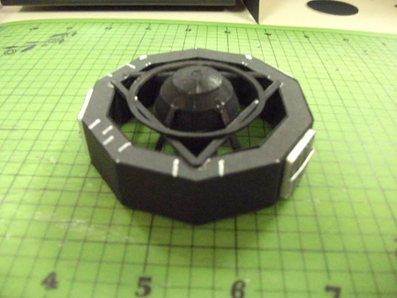
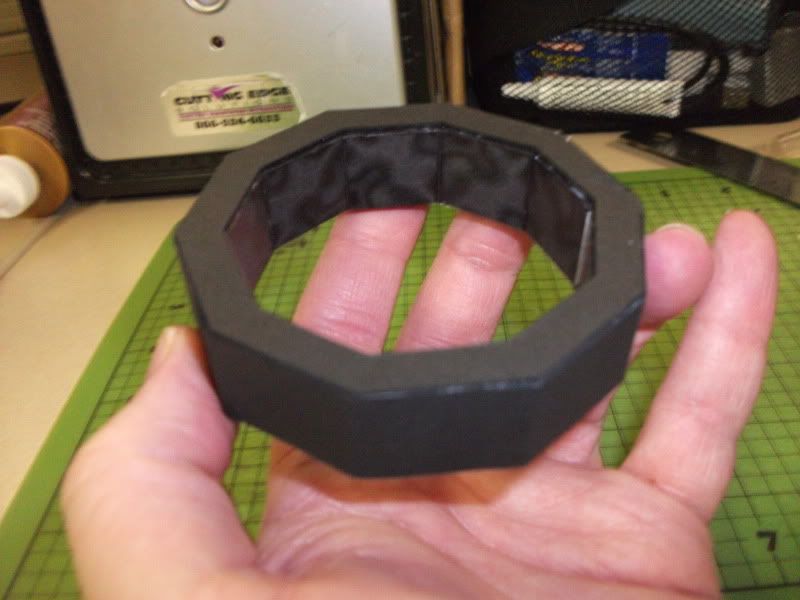
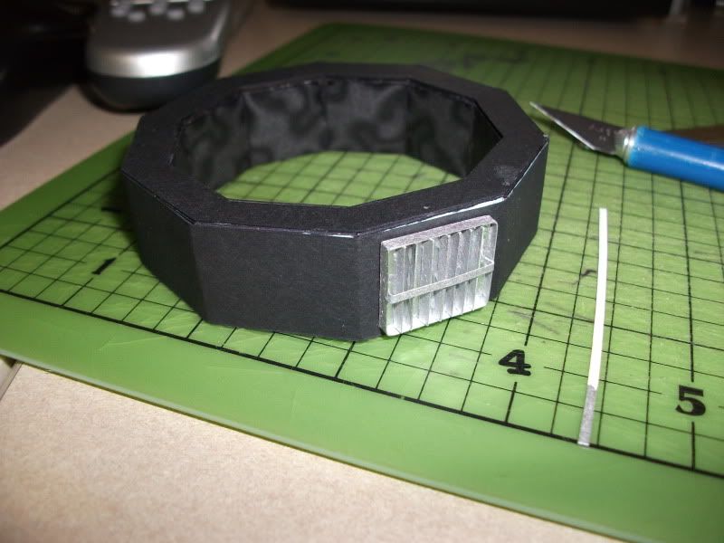
I covered the bus with black cardstock after assembly. Ton has a graphic representation of the blanket material, but I decided to use something else since the actual spacecraft's thermal blankets are matte in appearance. I did not score the edges of the cardstock, since the cloth doesn't sharply cover the edges of the spacecraft bus.

DSCF0131.jpg


Top and bottom also were covered with a layer of black cardstock. Be warned that this will cover up all of the placement makings, so adding equipment later will require plenty of reference to the original patterns.

DSCF0128.jpg


DSCF0133.jpg


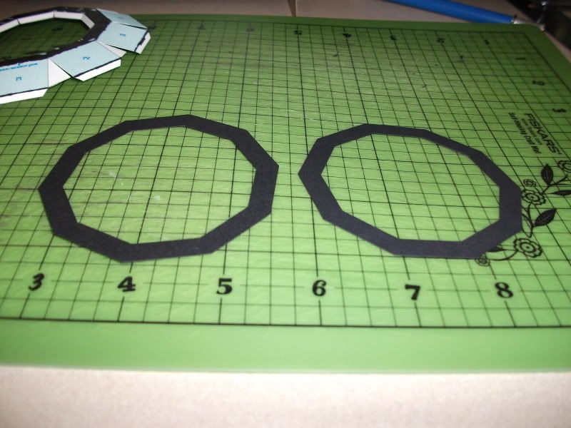
The central panels were not covered with extra card, as they won't be very visible later.

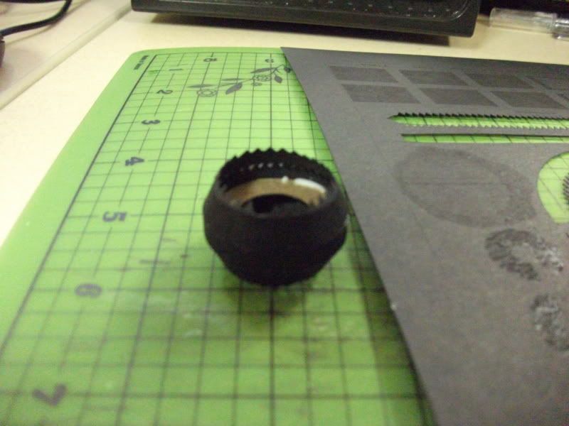
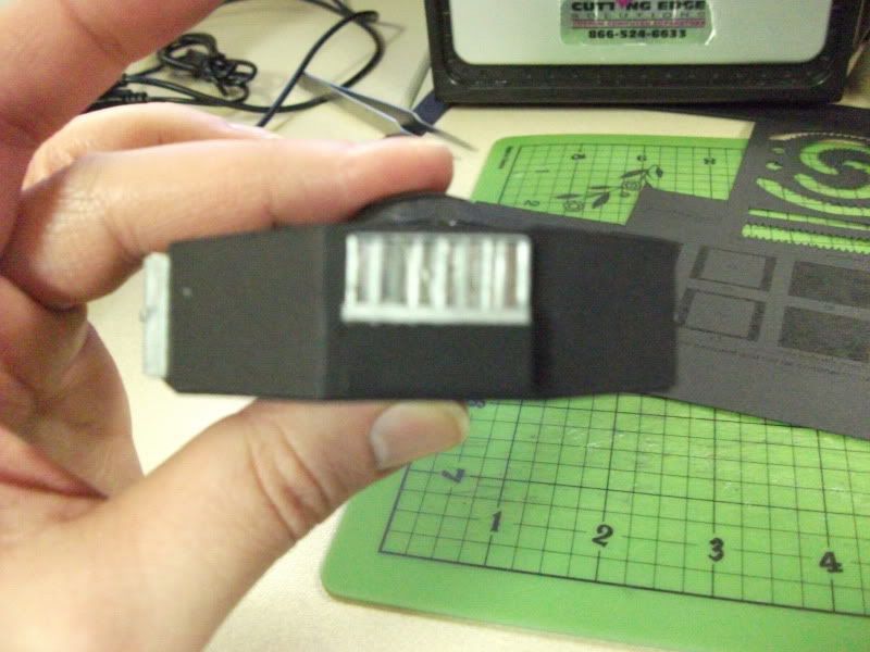
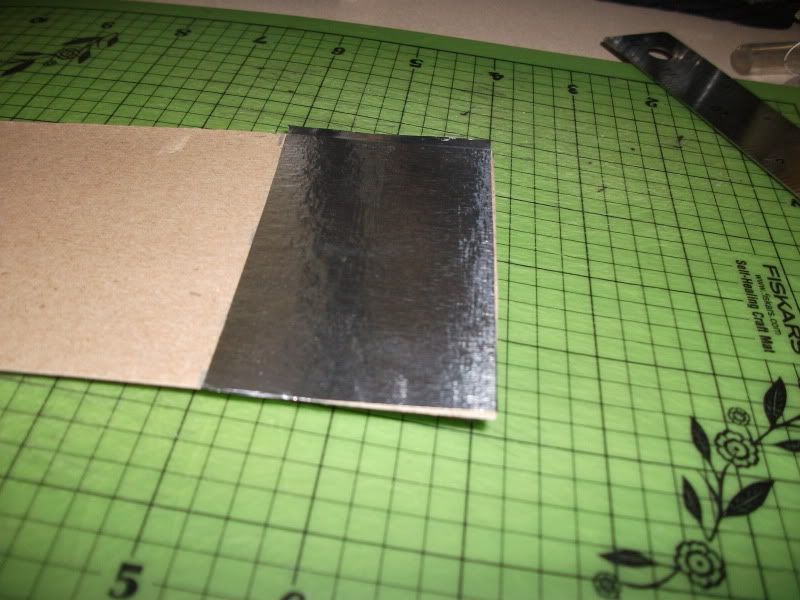
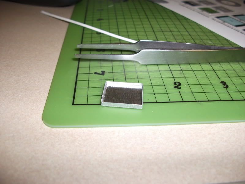
I decided that the thermal louvers on the spacecraft needed some three-dimensional detail, so I laminated aluminum foil to card and cut out the same size and shape provided for the louvers in the kit.

DSCF0134.jpg


Using a 3 mm strip of card (colored with a metallic Sharpie) I built the louver into a box.

DSCF0136.jpg


I then used more 3 mm strips to build up the louver's fins...

DSCF0141.jpg


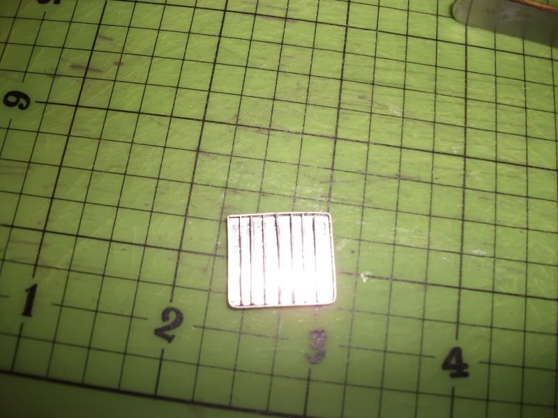
...and topped that off with another strip running horizontally across the fins.

DSCF0143.jpg


DSCF0145.jpg


It's really not that crooked. The front bar juts out slightly in front of the fins, which makes it look a little off. :mrgreen:
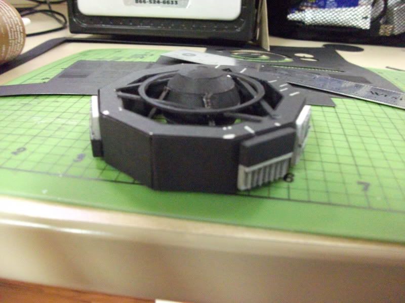
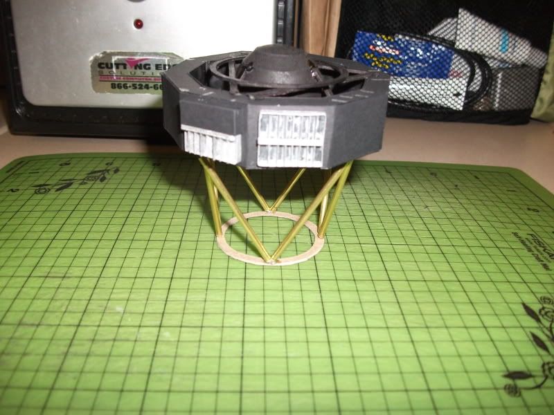
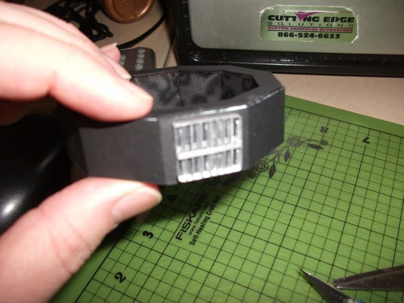
I'd say it looks like a decent representation:

1982_07251L.jpg


(The record cover is going to present challenges as well. The kit uses a photograph printed onto the bus, but I'm thinking about using the line diagram of the cover, shrinking it down, and printing it on gold stock. I want it to shine like the louvers do. As to how I'm going to shrink it to the correct size, I'm still trying to figure out.)

Some idiot then grabbed for his Xacto knife without paying attention. :eek:ops: I'm allowing the blood to clot before I build the next three louvers and move on to the hard parts: everything else.
Spoiler alert: I'm going to allow the booms to articulate, and there's going to be something attached to the bottom of the probe as well. Yogi can probably guess what that will be... ;)
 

Elliott

Senior Member
Jul 18, 2006
645
1
36
Great start for a build thread. You've got my interest. And, no, you're not an idiot; you're just related to me. :mrgreen:
 
Blood sacrifice completed early - the build should go well. Looking forward to seeing your artistic improvements to the "add-on" and the articulation of the arm and RTG boom.

Guilty - I have Ton's Voyager printed out (at 1:48 but still not started).

Now I need to check and see if I ever updated Jon with the simple Voyager that includes the extras (and the Magellan stack as well). Another diversion from building space stations and getting the COBE and WMAP models ready for the guys at NASA Goddard (note: they like 1:24 scale and options to simplify).

Yogi
 

jparenti

Member
Jun 3, 2006
54
0
16
41
Vienna, Illinois, USA
Short update on louvers and part placement

Here's hoping my sacrifice to the modeling gods helps me figure out how to make those booms move. I have a decent idea, so we'll see if it works. Not only will the articulation look good for demos, but it will hopefully negate the effects of gravity during display and storage. Only ten months in a fairly well controlled environment away from humidity has still taken a toll on the science boom of my first version. There isn't enough superglue in the universe to stop that sagging -- unless you embed the model in a block of it. The instruments at the end of the boom are the biggest problem -- they're heavy. The RTG boom really hasn't sagged much, mostly because the RTGs on the model are fairly light.
The other problem, of course, is the triangular attachment trusses on the bottom. I stiffened them with CA, and built them fairly thick, but they just barely hold up. As a purist, I neglected to attach them to a base, and that's my own fault. This time I shall do better.
I mentioned that covering the top of the bus was a bad idea if you want to see where everything goes. Solution? Print another sheet 1 and cut out the areas indicating equipment attachment points. This creates a mask:

DSCF0150.jpg


Lay the mask on the top of the bus, and mark the open holes with a metallic Sharpie:

DSCF0149.jpg


Repeat for the bottom.
Any stray offending marks can be covered up with black Sharpie later, or simply painted. Most of the marks are covered with parts anyway, so it wont show later.
(Note the dislocated vanes in the louvers. That's been fixed, too -- use strong glue and DO NOT handle the vanes after they've been attached. What I should have done was waited until later to attach the louvers, but live and learn. :eek:ops:
The fuel tank is next, and I've considered using a wooden ball, but we'll see how my construction skills are. I may still have to find a stand-in for the kit's tank, as I'm not terribly great at constructing spheres. There's also another decision to be made. The actual probe's tank is covered top and bottom with thermal blankets. The struts holding the tank and the tank isn't visible, just a bulge at the top.

pict0032.jpg


I'm still considering it but I like the look of the internal parts and would like to leave them visible, despite the departure from reality. It's something I can nail down for sure later, as adding the blankets wouldn't be an impossible thing to do even when the model is finished. Thoughts?
A few more hours should see the tank constructed and the struts attached.
 

jparenti

Member
Jun 3, 2006
54
0
16
41
Vienna, Illinois, USA
Tank half done:

DSCF0151.jpg


Tank mounted inside bus. I decided it looked decent enough to go on the model. I was concerned about my skills at this point, but printing the parts on black cardstock hides any imperfections quite nicely. Incidentally, it also makes the pieces very hard to see in order to cut them out.

DSCF0153.jpg


Structure above tank in place:

DSCF0154.jpg


Next, I decided to build the covers for the two half louvers. There are two of the four louvers that are half covered with black thermal cloth. (I have no idea why -- anyone else know?) Simple boxes made from black card:

DSCF0155.jpg


DSCF0158.jpg


One of the covers is on the top, one on the bottom -- once again, I assume it is related to the thermal signature of underlying equipment, but I'm guessing.
Next (tomorrow I hope) is the PWS antenna mounting. This will be basically a straight build from the kit, with the addition of some panels to hide the structure as seen here:

pws_crop_1.jpg


(This is the engineering model of Voyager, basically a third functional spacecraft that was never launched. It sits in von Karman Auditorium on the JPL campus, but in this shot was getting some sun outside during a JPL open house. Notice what looks like a fine mesh of threads inside the silver canister above the PWS mount. I wonder if an entire magnetometer boom is actually stowed in there?) :mrgreen:
 

jparenti

Member
Jun 3, 2006
54
0
16
41
Vienna, Illinois, USA
It's taken me longer to get on top of the build, due to unforeseen events. I am back now, and should be moving along faster now.
I was going to head toward the PWS mount next, but strayed a bit to the interstage connection struts. The kit parts are flat parts meant to be mounted to 1 mm card and attached to the bus. As sturdy as it may seem, the assembly will sag in a couple of months despite impregnation with plenty of CA glue.
I decided to represent the struts as tubes, which is what the struts are on the actual article, which I eventually intend to build from rolled paper. For now, and for the sake of prototyping, I have built a mock-up from brass tubing and wire, glued to a frame of black card:

DSCF0172.jpg


The ring on the bottom is for stability while the glue dried, and to give a better estimate of the size I will need for the injection stage itself. It's handy to have the struts fixed to something while handling the assembly during the build. Eventually, the ring will be cut to leave only four short sections attached to the struts. The spacecraft itself has these "feet", which connect to the injection stage.
(Now I understand many of you have qualms about using non-paper items in a model. I promise to the purists, I am still attempting to roll tubes that are satisfactory to me. When those are done, they will replace the brass parts on the final model. I simply needed a more sturdy platform while I build and test fit. Although it's so sturdy that I have hesitation when I think about not using it. :D
Here's the bus sitting atop the strut assembly:

DSCF0174.jpg


I used Ton's parts for measurement, and it fits perfectly. Notice that the struts are canted inward slightly. That's not a mistake -- the struts are actually canted, two toward the inside, two toward the outside. You can see what I mean:

blueprint_excerpt_1.jpg


That's all I have for now. I will continue (on the straight path outlined in the instructions) through the instruments on the upper side next, starting with the PWS mount.
If anyone has any suggestions or comments, let me know! I only have tentative ideas until I build something, and sometimes after that as well. :D