USS Selfridge DD 357 1/200 Scale

shoki2000

Active Member
Feb 6, 2004
324
0
36
Tampa, FL - USA
www.gremirmodels.com
...Normally, GreMir furnishes a nifty little base that you can simply cut out and assemble to hold the model upright. For some reason Maciej Poznanski, the author of this particular model nor Michael the owner of GreMir, added one to this one...

Well......
To tell you the truth, I didn't even realize that there is no base included in the kit until you mentioned it :eek:ops:
Other ships in GreMir offer have bases simply because designers included them in the model, but Maciej did not - he mounted Selfridge on this fancy wooden stand and probably didn't even think about other options...
What formers did you choose to include in the stand? I might try to modify one of the other stands for the Selfridge and include it as a PDF download on the page....
 

treadhead1952

Member
Mar 22, 2009
181
1
16
Las Vegas, NV USA
Hi Michael,

Yeah, that is sorta what I thought had happened after looking over the photos on the ProModel offering of the kit on the back of the book. I just took the base from the HMS Savage since it is roughly the same size as the USS Selfridge. I hope you don't mind me modifying the nameplate in Paint so that it would be useful in this case. As I stated in the posting with the ProModel book, it is the identical same kit, just arranged a bit differently to reflect the use of A4 Paper size instead of the A3 that we use over here.

Being that your kits are printable on demand makes this sort of thing quite easy to remedy as well as develop other numbers or characters on the hulls to provide for other ships in the individual classes. A bit of research on the part of the modeler and it is entirely possible to represent entire classes of different ships. One of the reasons that I am so sold on your format and presentation style.
 
Z

Zathros

Bases are easy to make off of the corresponding former of that section. In any vent, the ships potential is self evident. I look forward to seeing you button up the hull. :)
 

treadhead1952

Member
Mar 22, 2009
181
1
16
Las Vegas, NV USA
Hi All,


Sorry for being AWOL for a while, I was having a bad hip come up and needed to get replaced and now I am in the process of having that healed up and have been able to get back to doing other things that I enjoy, like sitting up at the model bench. I did get the hull on my Selfridge buttoned up finally. It really held no surprises. If you get used to working on the hull forms, adding the strips across the formers and like my choice of things, filling the hull up with card and balsa wood then sanding it down to the formers for a much better appearance not to mention gluing the bottom plates and hull sides on there.


I did chose to paint over the bottom of the hull with some Red Lead from Model Masters' Acryl line of paints so that it looks better than my printer handles the red from Gremir Models kit for some reason. I don't know why, but it comes out more of a brownish red than Red Lead Red should be. I just accept the limitation as a printer issue and work around it.


zathros

*****SENIOR ADMINISTRATOR*****
Staff member
Administrator
Moderator
Apr 5, 2013
13,499
9,551
228
Long time. That's some tough surgery to go through. The ships looks fantastic!! I hope to see more of it soon. Welcome back! :)
 

treadhead1952

Member
Mar 22, 2009
181
1
16
Las Vegas, NV USA
Thanks Zathros,


Yeah, it's the pits when the old body starts given out on you, or at least selected parts that are necessary for motivation.:curse:

I have been getting a few things accomplished on the Selfridge, the Pilot House got the first of a few things done that I wanted to change. They have a fire extinguisher tank printed on the front of the bulkhead, a bright red rectangle so I made up a real part by rolling up a section of bright red card to a tight cylinder and capped it off with a slight domed shape using a drop of Tacky Glue. Once it had dried enough to be handled, I painted it over all bright red with some Tamiya Acrylic paint, glued it down in front of the rectangle and then drilled a couple of tiny holes on either side of it in the bulkhead. I used a tiny section of copper wire, formed it into a exaggerated "D" shape with the back side left open, painted it black and installed it in the two holes for a securing rack. I also added more copper wire bits for the hinges and latches on each of the entry hatches to sort of detail them up a bit more. There was also a vent pipe of some sort that was printed on the bulkhead that I replaced with a section of copper wire glued into a hole in the deck and another in the bulkhead. All these little details got painted up and I moved on.


I used a section of laser cut paper ladder stock from Answer Models to start adding all the bits of ladder that dot the various locations about the ship. I also have some more of the same material that is cut into railings as well as stair type ladder ways that I will be using around the ship. I do this because while the kit does provide you with ladder ways that you can build up, I just plain suck at that particular task, unlike several other modelers that can whip them up to look perfect. I suppose that is from using Photo Etch so much over the years, I will look at finding ways to get me around such hurdles as that. :thumb:


I also started adding the little things to the decks like the bollards and hawse holes around the ship. The Zen of doing little stuff while a bit tedious does have it's place in detailing to make things look a bit less sparse and Spartan. There are a couple dozen of these tiny parts around the ship that require two to five parts each to make up. So getting them done and installed early on makes things a bit easier later on.


I also added the anchor handling gear and bow detailing to make things easier on the front end of things. I have a section of brass chain that I got from Model Expo long ago that I use for anchor chain on destroyer sized ships in this scale. That same chain would probably be used as stay chains on larger capital ships anchor chains, but for this purpose it is just fine. I use a product called "Blacken It" also from Model Expo to change the color from brass to black. It only takes a brief dip in the stuff, rinse it off and dry it then it is ready to go. With the kit parts installed, a couple of holes poked into the decks to allow terminal locations for my anchor chain, I could install it around the gear and add the break water and I was set on the bow end of things.


zathros

*****SENIOR ADMINISTRATOR*****
Staff member
Administrator
Moderator
Apr 5, 2013
13,499
9,551
228
Great pictures. What a nice model to have! :)
 

treadhead1952

Member
Mar 22, 2009
181
1
16
Las Vegas, NV USA
Thanks Zathros,


It is another fine Gremir Models version, although I did go out and purchase the Pro Model version as well to see if there was any differences (there isn't, they are alike as two peas in a pod). I do like being able to willy nilly print off extra pages at the drop of a hat with the Gremir Models version though. Padre built it up a few years back, his thread has been relegated back to about page 21 of the Ship Models forum section here.


http://www.zealot.com/forum/showthread.php?t=135411


I am going to be using RB Models 20MM Oerlikon single mounts, some generic brass 40MM Bofors barrels and 5" brass generic barrels to fill out my weapons though. I never was worth a hoot when it came to tightly rolling up gun barrels. I do like to add extra detail parts to these things though. Reprinting pages lets me clip extra hatches, doors, and other parts like ventilation screens to add as well as using copper wire to make up hinge details, latches, piping and other small stuff that is lacking.


I did get into another one of those tedious parts of this particular ship build. The two lower deck spray shields that run back one either side of the ship require you to cut the outer part free from the hull side, add an inner part and then cut out and fold and glue up a whole lotta' tiny little triangular braces to support the length of the spray shields. This does keep them raised off the deck just a little bit and add another one of those fussy little details we ship modelers seem to dig tinkering at.


Tomorrow I will start working on getting the stacks raised and adding some more detail to the Pilot House, got a whole 'nother two levels to go up on that one. There are a whole bunch more details to add to it as well. :thumb:
 

zathros

*****SENIOR ADMINISTRATOR*****
Staff member
Administrator
Moderator
Apr 5, 2013
13,499
9,551
228
Those Oerliko's were some scary guns, especially that ejection procedure before reload. Nice gun, good thing it was replaced! :)
 

treadhead1952

Member
Mar 22, 2009
181
1
16
Las Vegas, NV USA
Hi Zathros,


They were pretty scary on the other end as well, with a fast rate of fire and healthy sized projectile. I like RB Models version of the single mounts, only 6 parts to come up with a credible looking model Oerlikon is not bad.


treadhead1952

Member
Mar 22, 2009
181
1
16
Las Vegas, NV USA
Hi All,


I managed to get the two stacks built up then mounted as well as add the upper works of the Pilot House. The parts are easy to build up and if you are like me, that goes a long way to making a model more fun. I did add some pieces to the forward stack on the bottom end to block it closed so that you can't see into the base, just through it as it was. Making up the range finder and it's mounting was also not a hard thing to do, just a bit more involved with more parts to put together. I will be adding a bit more detail to the upper operational area to help what is just drawn in place to represent detail. I will also be using sections of ladder material to replace the printed on detail there. Making things appear more 3D helps things along in detailing.


I also added some ventilator hoods, the Engineering Deck House that mounts the aft funnel and the two torpedo launcher rack bases. From some photo studies that were done when the ship was undergoing her rebuild at Mare Island after having her bow blown off by a Japanese Long Lance Torpedo, I get to see a lot more details to add here and there. I will point these out as I come to them.


I started adding ammo and equipment lockers, the kit supplies you with plenty of them to add details with. Busying up areas of the ship as you go along as long as it agrees with the photos of the ship is always a good thing.
 

zathros

*****SENIOR ADMINISTRATOR*****
Staff member
Administrator
Moderator
Apr 5, 2013
13,499
9,551
228
Some real close ups of tose Oerlikens would be nice! :)
 

treadhead1952

Member
Mar 22, 2009
181
1
16
Las Vegas, NV USA
Hmm, gee. I will see what I can do about that one.


And just to show you that my head and heart are in the right place, here is an "Official" US Navy Training Manual illustration for you to enjoy for reference purposes.


zathros

*****SENIOR ADMINISTRATOR*****
Staff member
Administrator
Moderator
Apr 5, 2013
13,499
9,551
228
Looks freakin' great!! :)
 

treadhead1952

Member
Mar 22, 2009
181
1
16
Las Vegas, NV USA
Thanks Buddy,


I thought you might like that "Official" US Navy photo since it is much more highly detailed than my tiny models.


I started adding more parts and details to my little project here. With the two 20MM Oerlikons on the sides of the Pilot House made up I moved to the second deck on the top of the Engineering Deck House. After making up the deck as per the kit parts I started to look around and ran into a little issue. I had one source that said the ship had 4 20MM's, another said 6 and yet one more came up with a total of 8! Now I am not exactly a rivet counter but, I did want to have a somewhat accurate count on the weapons she was supposed to have carried. :boom:


Fortunately, I did have a source of inquiry that I could use. I posted my question over on the Model Ship Forum and Dick J, one of the regulars was able to answer my question. Pointing out this photograph, which I actually already had, just not studied closely enough, answered my query.


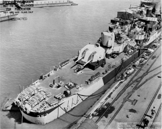
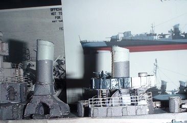
Blowing it up and looking around the aft stack I was able to see that the author of my kit had missed the boat when it came to the upper deck. What he had produced as a three leafed clover shape was in reality a four leafed clover shape with a rectangular shaped end on the aft side. Instead of two 20MM Oerlikon mounts it had a total of 4. I also noticed that the armor plate around the deck was not all smooth in appearance but actually had raised portions all about the sides. These were where the armor plates had been originally riveted together then in later construction, welded together. It make for a distinctive shape and appearance.
'
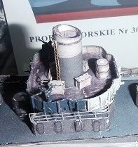
If you look at the second photo in my previous post you can see the three leafed clover appearance of the upper deck as issued in the kit. After noting the differences, this is what I came up with.


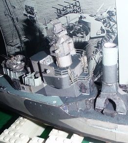
Since I had noticed the difference in appearance of the armor plate on the section of upper deck, I needed to make changes to the same armor around on the Pilot House gun positions. All of these changes were just made by gluing some tiny cut strips to the plate around the various locations on the ship. When I install more of the stuff on the after Deck House, I will have to do the same thing again to make it look as it should. Just a minor change but it does make a lot of difference in the appearance of the model.


I also added railings around the Engineering Deck House roof and then came to the consideration of just how the crews to serve those 20MM's might get to station. While there are two ladder ways that go up on the forward end of the Engineering Deck House there doesn't appear to be any sort of a way up from there to the upper deck. Rather than condemn the sailors to climbing up the stack ladder in a timely manner, I added a square cut to the upper deck section in front of the stack and attached a section of stair type ladder way and a railing to the underside. That would allow my swabbies to race up to their firing stations in a timely manner and man the guns in time of attack.


I also added railing sections to the after end of this deck house, added the control panel detailing on the upper control area ahead of the Range Finder and started studying these photos a whole lot more closely to try and pick out other things that might make a difference in the appearance of my model project.


treadhead1952

Member
Mar 22, 2009
181
1
16
Las Vegas, NV USA
Hi All,


I have been tinkering at my project here for a couple of days. Making up and adding a couple more 20MM Oerlikons to the upper deck over the Engineering Deck House Roof was one easy fix.


I also had to build up the main turrets and added the brass 5" barrels for them. As I like to make these things look a bit more detailed than a plain printed item, I used extra copies of them to clip out all the hatches, doors, and other projections so that I could glue them down. I also recessed the areas around where each of the barrels went by using two extra reprints of the front of the turret faces, cutting out the areas on the one the I was using for the outer shell, cutting out the first inner piece and then drilling the holes for the barrels in the third layer down. By edge shading the holes that I cut out and gluing things up, it now appears to have a recess where the barrels go up and down in the turret face.


treadhead1952

Member
Mar 22, 2009
181
1
16
Las Vegas, NV USA
Hi All,


Using a photo of the ship as she was putting out to sea from Mare Island after her refit I noticed and selected some details that I wanted to add to my model, namely the modified stacks. While the kit provides serviceable items, when the ship put to sea, there were differences.


At the top of each stack was some sort of venting that was not provided for in the kit. Adding it was a matter of a little cutting and fitting of some card and a little painting. I also added the kit provided stack projections on the after side of each and the large main steam vent pipe on the rear of the forward stack. These items make the stacks look considerably more busy.


I also added the copper wire supports and bracing that the kit calls for on the Templates Page. There were also a couple of guards beneath the position lights on either side of the Pilot House. Adding the two floatation net baskets on either side of the armor around the 40MM Quad Bofors Mount was another little detail I could add at this point.