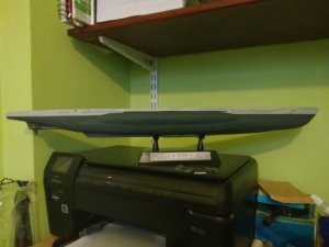
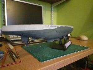
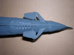
U-Don's U-Boot typ VII C

Papa Mashy

Masher of paper
Jul 29, 2018
157
269
40
East Anglia, UK
Propellers!
These were fun.

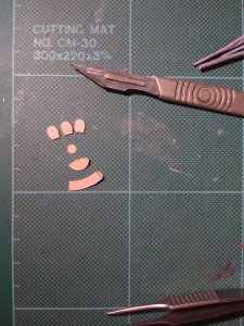
They are fairly simple regarding the parts.
IMG_20180929_201326864.jpgIMG_20180929_212358431.jpg
The tricky bit is shaping the petals and positioning.
On this model there is a left and right pitch direction and each petal is required to be shaped into a concave followed by the appropriate twist.
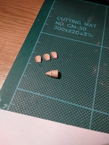
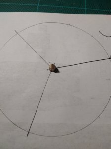
Add to that there is no positioning marks on the cone pieces for correct alignment.
I came up with a super quick solution of marking out in thirds by just using a scrap of paper and dusting off the old protractor.
IMG_20180929_212340303.jpg
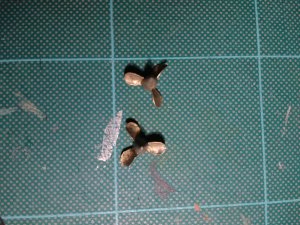
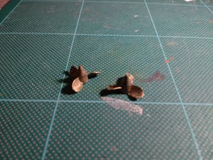
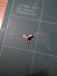
The forming and attachment of the petals was just a case of referring to reference pictures and replicating by eye.
No major problem.
IMG_20180929_213057056.jpg
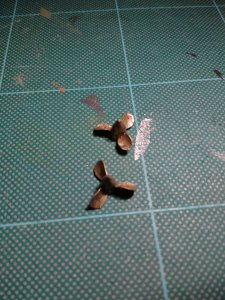
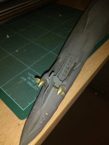
Finally. Painted up.
IMG_20181007_205054732.jpgIMG_20181007_205203000.jpgIMG_20181007_205233591.jpg
The paint used are:
1. Grey primer
2. Brass metal (metallic)
3. Matt Clear coat
4. Thin wash of Seagreen mixed with Anthracite black

I have opted to give a heavy weathering to the propellers as I want to replicate a returning boat from patrol look rather than factory fresh.
I'm reasonably pleased with the outcome.

More pics to come once installed.
 
Last edited:

zathros

*****SENIOR ADMINISTRATOR*****
Staff member
Administrator
Moderator
Apr 5, 2013
13,498
9,549
228
In the maritime world, they are referred to as officially "screw propellers", this was done to differentiate between the original screw propellers and "paddle wheel boats". "Screw propellers" is the proper modern definition. What is said on board a ship is usually "screws", as it is shorter, and why waste time when a second can count. Don't trust me, Google it, find out for yourself. There is a difference between idiomatic, and colloquial usage, and "official standards of reference" which exist across the industry of the various English speaking countries involved, that being said, it still is "screw propellers".

The only thing I would do is make the leading and trailing edges as thin as possible. If you look a these things in real life, you would be surprised to see how sharp the edges are. This is to avoid cavitation, which leads to being heard, and efficiency of the screw propeller itself. :)

Actual U-boat screw propeller:

U-boat screw propeller.jpg
 

zathros

*****SENIOR ADMINISTRATOR*****
Staff member
Administrator
Moderator
Apr 5, 2013
13,498
9,549
228
My answer based on years of naval interest :hammerhead: guess the coloquial has infiltrated most of the literature as well! Thanks for clarifying!


It's the day to day spoken references the run the operations. What's in the books is another story. I am certified in a few trades, and the official names for tools, and procedures match nothing that is spoken in the shops. It's good to know both though, just makes you well rounded. The modern propeller was born when an original full helix screw propeller hit rocks, and when many of the Helix pieces broke off, the boat picked up noticeable speed, this lead to the birth of the modern propeller, which were addressed as "screw propellers" as they originally looked like long screws, and a name was needed to differentiate from paddle wheels. The new experiential cycloidal propeller (bottom pic) theories are in a class of their own! ;)

original screw propellers:

1794 Patent Screw Propeller.jpg Early patented screw propellers that lead to modern propeller.jpg

Cycloidal Propeller:

Voith-Schneider-propellers-installed-under-the-ship-hull.png.jpg
 

micahrogers

Moderator "Where am I, and how did I get here?"
Staff member
Moderator
Jul 12, 2012
3,772
4,639
113
Shannon GA
on a boat, they would be referred to as screws, why say the proper "screw propeller" when it is easier to just say screw. I watched an O6 full bird Captain dress down an 08 who called them propellers at a change of command ceremony for a DDG. just as they would never say "all ahead full"... the order would be "make revolutions for... " and the speed wanted... let the engineering dept make the decisions on how to follow the order.
 

zathros

*****SENIOR ADMINISTRATOR*****
Staff member
Administrator
Moderator
Apr 5, 2013
13,498
9,549
228
Those ship captains know how many revolutions will make that ship go at. There is little room for guessing. Even more so in subs, which do not have waves and air to deal with. Currents are another issue, but that's in everything. The movement is still relative to the ship and immediate water around it. ;)
 

micahrogers

Moderator "Where am I, and how did I get here?"
Staff member
Moderator
Jul 12, 2012
3,772
4,639
113
Shannon GA
too true, I know we had a killer 15+ knot cross current that threw our navigation off by 2 or 3 miles every 6 hours...the one thing a sailor hates to hear the captain say.... "all three turbines to 120% and put it all to the screws, rig the boat for rough seas"... and the weather that day was dead calm.....
 
  • Like
Reactions: Cybergrinder

Papa Mashy

Masher of paper
Jul 29, 2018
157
269
40
East Anglia, UK
Small update..

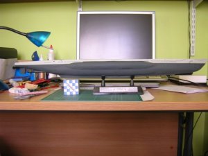
Main paint is on the hull.
I've done some experimentation with applying wash, not necessarily to 'dirty' but more to accentuate. Anyway, I'll leave that for later once I've finished assembly.
IMG_20181014_151006839.jpg
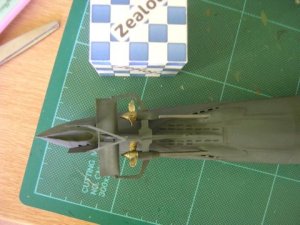
Prop shafts (or should that be screw shafts? ;)) & turning things for propulsion installed.
IMG_20181014_150724001.jpgIMG_20181014_150638091.jpg
There is some more cosmetic work to do to tidy up, but I'll revisit later once I've finished with the rear assembly. You can see I bent the right shaft during assembly which needs repainting e.t.c.
In hindsight I think I would make the screw propellers from thinner paper next time and sand the edges or perhaps crush to a finer edge. (as suggested earlier by Zathros)

Now to make the twin rudders and rear dive planes...
 
Last edited:

Papa Mashy

Masher of paper
Jul 29, 2018
157
269
40
East Anglia, UK
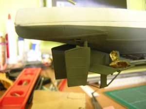
Rudders, rear dive planes and supports installed.
I'll not lie. Looks relatively straight forward, but getting everything symmetrical was a bit tricky.
The rudders were ok, as I could use the support iron work to line up correctly, the dive planes however were much more troublesome. They are supposed to go before the rudders, but I would recommend not following that leave the dive planes till last. That way you have better reference points for their installation.
Still more painting to do and repair work..

DSCN2178.JPGDSCN2183.JPG
Just used an empty biro to make the panel lines before assembly.
DSCN2182.JPG
Anchor and bow dive planes next...

Then I've got a problem. What to do with the deck...
DSCN2184.JPG
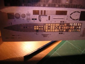
If I glue it on as is, I can't paint it as the detail will be lost. Also there won't be any depth apart from the hatches e.t.c. that will will added.

If I opt to cut out every hole and slot I may go mad.
Thoughts anyone?
 
Last edited:

micahrogers

Moderator "Where am I, and how did I get here?"
Staff member
Moderator
Jul 12, 2012
3,772
4,639
113
Shannon GA
Okay, try burnishing a 3d texture into the parts... use an empty ball point pen, place the part on a soft but firm surface, like a plastic cutting mat, and use heavy pressure to push down against the ports and holes, forming small indentations in the paper
 

Gandolf50

Researcher of obscure between war vehicles...
Staff member
Moderator
Jan 28, 2013
1,327
1,576
96
New Mexico USA
Then I've got a problem. What to do with the deck...

If I glue it on as is, I can't paint it as the detail will be lost. Also there won't be any depth apart from the hatches e.t.c. that will will added.

If I opt to cut out every hole and slot I may go mad.
Thoughts anyone?


Okay, try burnishing a 3d texture into the parts... use an empty ball point pen, place the part on a soft but firm surface, like a plastic cutting mat, and use heavy pressure to push down against the ports and holes, forming small indentations in the paper


Wise advice from micahrogers... and I would add, DO BOTH and also double print and stack for depth greebles where possible like they partially did on parts 23-24 27-28 etc. it also looks like the hatches are done also. Personally, I would toss the printed life-lines and replace with the proper size ( or as close to ) wire, which you can CV glue together.
 

Papa Mashy

Masher of paper
Jul 29, 2018
157
269
40
East Anglia, UK
Gah! Slot cutting!
DSCN2207.JPG
Have been doing the combo of burnishing and cutting. Zzzzzzzzzzzz
It will be worth it though, I know.

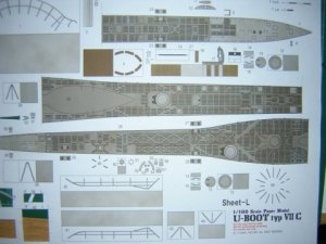
The darker grey area (with the slots) represent the wooden planked area on the real thing. Therefore I will separate this and glue to thin card to raise it up from the aft "steel" section for depth.

I toyed with adding some of the retractable bollards (part 23/24 e.t.c) in the "up" position, but have discounted the idea. I can always change my mind later...

The bow planes are done, so it's just a matter of getting on with the deck now.
DSCN2208.JPG
 
Last edited: