Turnouts & LEDs

Woodie

Active Member
Mar 23, 2001
2,093
0
36
Northern Rivers NSW Australia
Guys,

I'm looking for a way, on my control panel, to indicate which track each trunout is switched for. "Momentary on" toggle switches return to the middle position, and "monetary on" push button switches are just that. a push button.

I'm using Peco electrofrog turnouts with Peco turnout motors.

Of course, my control panel will have a track diagram, with turnout buttons located at the turnout on the diagram. I'm thinking of using the "momentary on" buttons, with two buttons per turnout, one located on each frog on the diagram. i.e. want to switch for the "curved" frog of the turnout, then push the button on the "curved" part of the diagram. But I also want to put a little LED or globe on each part of the turnout diagram, to show which way the turnout is curently switched.

Any ideas? :confused:

Currently using DC control not DCC, but will eventually....... umm.... eventually..... go DCC.
 

60103

Pooh Bah
Mar 25, 2002
4,754
0
36
Brampton, Ontario, Canada
Visit site
Woodie, if your point motors have the extra bit of wire sticking out the bottom, you can add a Peco switch. They have both SPDT and DPDT versions (I think). (You may have to use these with your electrofrogs to switch the frogs if you get shorts.)
You could power the LEDs with a 1.5V battery (rechargeable D cell?)
 

Woodie

Active Member
Mar 23, 2001
2,093
0
36
Northern Rivers NSW Australia
Yep. Peco have the DPDT swtiches to mount under the motors, and I use them for switching polarity when required (with appropraitely insulated track), so I'm familiar with them. I'm going to have around 35 turnouts, so expense comes into it here, too, of course. :thumb:
 

Woodie

Active Member
Mar 23, 2001
2,093
0
36
Northern Rivers NSW Australia
Dash,

Thanks for that link, and yep. Lots of goodies on that one. :D

However, the LED circuits on that link for turnouts use an "always on/on" switch for throwing the turnouts, and basically requires a CDU for EACH turnout. (resistors and two capacitors for EACH turnout), and where a 1000 ohm resistor and LED are placed across the applicable "on" circuit to indicate which leg is switched.

From that site, I use a CDU like this one. (the top half, with LED charged light).

CDsimple.GIF


Note the use of "momentary on" switches, which is the config I want to use, and utilize just the one CDU for all turnouts. remembering that having 35 + turnouts, has a multiplier cost effect here.

A single CDU with momentary "on" buttons (@ 50c each * 2 per turnout) + wire. If I can get an LED powered in this somewhere, the better. :):) :thumb: :cool:
 
F

Fred_M

You will note, 1 MC switch per coil. That what I mean by firing one coil per unit. This is designed to fire one coil at a time. Fred

From that same link here's a CDU with directional LEDs.
ToggleTwin1.GIF

and frog control
ToggleTwin3.GIF
 
Hi Woodie,
I think you want to use one of the isolated contacts on
the point motor to indicate the turnout position with
a separately powered circuit. My understanding is that
Peco offers a DPDT auxiliary, one side can power your frog,
the other side can power your LED's. :thumb:

Both contacts are isolated from the coil circuit. Whether or
not you use a CDU should not affect the indicator circuit. :)
 

TrainClown

Member
Apr 17, 2003
861
0
16
66
Saskatchewan, Canada
Visit site
Hi Woodie.

I remember seeing a post, I think it was by shamus. He controlled his turnouts, not with buttons, but with a probe. On the track plan on the control panel, he has a nut and bolt where you want to put a button, with the head of the bolt showing on the track plan, and the negative wire that runs to the switch machine hooked to the end of the bolt, inside the control panel. Beside the panel is the probe in a holder. The probe looks like a pen, with a metal tip and a wire coming out the back end that is hooked to the positive power supply.

To activate the switching machine, you simply take the probe, like a pen, and touch it to the bolt head of the switch you want to activate. Just a touch is all that's needed to through the machine. The advantage with this is that bolts are cheaper than buttons, but they are also smaller, and your control panel can be made smaller and take up less room.

maybe someone else can give you there thoughts on this system. What do you guys think about the probe method?

TrainClown :wave:
 
F

Fred_M

Yep TC, that was Paul's, it was cool. I myself use "choke" cables mounted in front of the switches in the facia. Cheaper and more reliable IMHO. I have been pineing on them fancy brass interlock handles, but haven't loosened the purse strings for them. Fred
 

Woodie

Active Member
Mar 23, 2001
2,093
0
36
Northern Rivers NSW Australia
dash10 said:
You will note, 1 MC switch per coil. That what I mean by firing one coil per unit. This is designed to fire one coil at a time. Fred

that is correct, Fred. however, unless I am mistaken somehow, that circuit requires a set of capacitors for EACH turnout. Effectively, a CDU for EACH turnout. at $3 a pop for each capacitor, times 35 - 40 turnouts........

With the "momentary on" system, it requires only ONE CDU for the entire layout.
 

Woodie

Active Member
Mar 23, 2001
2,093
0
36
Northern Rivers NSW Australia
TrainClown said:
Hi Woodie.


To activate the switching machine, you simply take the probe, like a pen, and touch it to the bolt head of the switch you want to activate. Just a touch is all that's needed to through the machine. The advantage with this is that bolts are cheaper than buttons, but they are also smaller, and your control panel can be made smaller and take up less room.


TrainClown :wave:

TC. yep. I remember that two. :cool: Shamus' system is the equivalent of the "momentary on" button. i.e. the circuit is "on" only while the button is pressed (or the probe is in contact with the bolt). And the "momentary on" buttons I intend to use are only 25c US each.
 

Gary Pfeil

Active Member
May 7, 2001
2,510
0
36
Boonton NJ
Visit site
Hello, Ever feel like you were invisable and no one could hear you? Woodie, in your other thread on cdu performance, I mentioned the stud and probe method, from the 50's by the way. I've used it for 30 years. Major advantage besides cost is ability to use higher current, without welding contacts. It's current you need to throw those multiple machines. Rectify to dc so you can use diode matrix's. As far as the leds to indicate the throw of the machines goes, David had it right so I never responded. Use the extra contact to light your led, use a seperate power supply, it could be almost anything available. No real power required.

Gary
 
F

Fred_M

Woodie said:
that is correct, Fred. however, unless I am mistaken somehow, that circuit requires a set of capacitors for EACH turnout. Effectively, a CDU for EACH turnout. at $3 a pop for each capacitor, times 35 - 40 turnouts........

With the "momentary on" system, it requires only ONE CDU for the entire layout.
Maybe you need us to do you a cap run? Here 2200uf 35 volt caps are 85 cents each in 10+ quanities. http://www.allelectronics.com/matrix/Radial_Electrolytic_Cap.html . I order stuff from them all the time. But your point is taken. Hook then up to the frog switch. Another easy way if you don't mind the leds being dim at low power is to use the fact that the frog is alway hot to one or the other routes. So you could put a full wave bridge, a limit resistor, and LED between the points and each switched rail. Follow that? But then each turnout requires 2 full wave bridges which may cost about as much as 2 caps in Oz? I use my eyes for route control. That's the cheapest. We hear you Gary. :wave: Fred
 

TrainClown

Member
Apr 17, 2003
861
0
16
66
Saskatchewan, Canada
Visit site
Sorry Gary, I never saw your other thread. I never new this was a thing from the 50s. Interesting to note that it can handle higher current. So dose it work any better if you were to use brass or copper bolts?

TrainClown ;)
 

Gary Pfeil

Active Member
May 7, 2001
2,510
0
36
Boonton NJ
Visit site
Hey TC, I just use brass bolts and capture the wire to the switch machine coil between two nuts on the rear of the control panel. I don't have much tech knowledge of the whys and wherefores but thru experience I've found that dc arcs much more than ac when you break a circuit. That arc is what welds the pushbuttons we use to throw turnouts. It happens when you release the button. Since we use dc if we want diode routing, we have to deal with that arcing. Diodes can be placed across the switch contacts to act as snubbers, but I've still welded. When a button welds itself, the coil on the switch machine burns out quickly. Cap discharge systems prevent that by their nature, there is a burst of power then no power, or just the recharge power. However, even tho so many swear by them, I've never seen much reason to deal with them. I only use twin coil machines in my hidden staging areas, and use panels to control the turnouts there. So the probe and contact method works well there. If you want the controls along the fascia, that would be different.

Anyway, the reason you can have much more current is that there is no switch contacts to weld. Tho I did have my probe wire weld to a screw head once. You want to make sure the probe isn't still on the screwhead before you walk away! I bought a 12 volt 8 amp transformer for about $50. Not cheap, but its a heck of a xformer. I fused its output at 6 amps. As I stated, it throw 5 twin coils no problem, I don't have a ladder with more turnouts. No recharge time as there are no caps. I do control several Atlas machines with Atlas pushbuttons with no problem, as those machines don't draw much current. I just run the 10.5 volt dc bus wires all around the layout and tie into them whereever needed. The 10.5 volts (after rectification) are plenty to operate the Peco machines, despite their litarature stating 12 to 16 volts, I believe. I also use the same power supply to run all my slow motion motors along my mainline.

I do have a couple Acme pushbuttons which seem to hanle current better than typical pushbuttons. I got these at the hobbystore, they are made specifically for model railroad use. They consist basically of sprung phosper bronze strips and a red and a green plastic button. They attach to the panel and when you push one of the buttons it makes contact, when you let go the spring tension is apparently sufficient to reliably break the contact. I have welded the Rix buttons on their first use. But the Acme button is only used to operate one turnout at a time, a NJ Int. machine. Don't know how it would stand up to multiple machines.

BTW, When my original transformer wouldn't throw 3 machines (it was 12 volt, 1 or 2 amp) I tried 16 volts, then 24 volts, both at 1 amp. Voltage didn't matter. Amps are what you need. I measured a Rix machines resistance, its practically zero. So it draws a lot of current. Haven't measured other makes but assume they are all similar.

Gary
 

Woodie

Active Member
Mar 23, 2001
2,093
0
36
Northern Rivers NSW Australia
Dash,

2200 uF 16WV cap in Oz $1.65 AUS ($1.15 US). Not powerful enough.

2200 uF 50 WV $3.95 AUS ($2.75 US).

Doesn't seemthere's an easy (meaning cheaper!!) way around this if I want the LEDs.

hmmm... **puts thinking cap back on and checks wallet balance** :cry:
 

shamus

Registered Member
Dec 17, 2000
3,489
0
36
87
UK
Woodie said:
Guys,

I'm looking for a way, on my control panel, to indicate which track each trunout is switched for. "Momentary on" toggle switches return to the middle position, and "monetary on" push button switches are just that. a push button.

I'm using Peco electrofrog turnouts with Peco turnout motors.


Currently using DC control not DCC, but will eventually....... umm.... eventually..... go DCC.
Hi Woodie,
If as you say you have the Peco electrofrogs and PL10's (Motor's) then you can place the PL13 underneath the PL10 which is a switch which can be used (I use them) to light up an LED placed on your control panel. This system uses a separate 12volt transformer to light the LED's up with. If you need to know how to wire this system, let me know.
Shamus
 

Woodie

Active Member
Mar 23, 2001
2,093
0
36
Northern Rivers NSW Australia
Thanks for that Shamus. And yep. Aware fo the PL13s, and use them, on a few turnouts to switch polarity. I was looking for a "minimal cost" option, but it looks like it's "swings and roundabouts". I'd prefer to do something at the control panel level, as some fo the turnouts are up to 6 metres from the control panel, and using a switch or whatever at the turnout, would involve wiring to and from the turnouts. The "momentary on" buttons (50c each X 35 + turnouts), with a single CDU ($10) (at the control panel) with a "common" bus wired to each turnout, and dual wire to each turnout is the least wiring too, and is the easiest and cheapest, but appears not to be able to support the use of LEDs as turnout mode indicators as part of that circuitry.

The "momentary on" solution is comparable to the "bolt & probe" operation, such as you use.

If I want the LEDs, then it looks like it's not only just the cost of the LED + 1000 ohm resistor, a bit of wire, and drill a few holes in the control panel, but will require either a separatly wired and switched system (and cost for 35 + turnouts), or $2.50 ON/ON switches + basic CDU for EACH turnout + LED and resistors.

hmmmm.... methinks I'll do some sums. :(
 

Pete

Member
Jun 2, 2001
150
0
16
56
New Brunswick, Canada
www.hioutput.com
Hi Woodie
Here's a couple of ideas...mebbe.
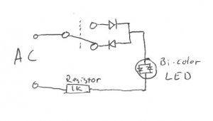
Rather than using the PL-13, you could wire in an inexpensive (if there is such a thing) latching DPDT relay with the coils on the switch motor, and it would switch power to the LED's. The latching types will stay in one position until a shot of current hits the opposite coil, and 'latches' it in the other position. This relay could be placed wherever it was convenient. As well one side of the PL-13 could be used for this, but like you said, then you would be running miles of wire.
For LED's you could use some bi-color (red/green) ones on your panel to indicate which way the turnout is thrown (green for main, red for diverging). They could run off of AC power, and use one side of a DPDT relay and a pair of diodes to control the polarity flowing through the LED (see crude drawing below).
I'll send you a PM concerning relays and LED's.
Hopefully you, or someone else can use these ideas...

Pete
 

Attachments

  • sm polarity.jpg
    sm polarity.jpg
    12.9 KB · Views: 118