Trix U30C engine problems

foxman

New Member
Dec 29, 2001
6
0
1
Visit site
I have recently purchased an older trix U30C (it was made in mid to late 70s) and decided to put MT couplers on it. When I put it back together it didn't work. I have done everything I could think of to get to work, but to no avail.
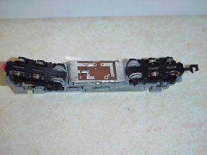
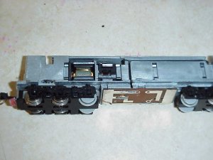
This loco design has a circuit board under the fuel tank and the pickups are small copper stips attached to the wheel assembly.
I am at a lose. I tested the motor and it still works but cannot for the life of me figure out how to get power to and from the motor.
This was a great runner and I would hate to lose it.
Does anybody have any experience with this type of loco, or know of anybody that I could contact or email or is there a web site or anything???
I can email pictures of the setup if needed.
I really frustrated with this...
Please help!!!

foxman
 

kettlestack

Member
Jan 18, 2002
859
0
16
84
Scotland UK
Visit site
Hi Foxman,
Although I have no experience with that particular make of model other than steam locos in N gauge I might be able to provide a few pointers.
1) Post a picture of the disassembled loco into this thread. Others may then input their ideas.
2) As it is was made so long ago the circuit board is probably just a diode assembly to make the headlights work according to direction of travel.
3) Ensure that no metal parts on the circuit board can come into contact with the (possibly) metal chassis. ie, avoid short circuits on it.
4) As you told us that all you did was fit Kadee couplers either the metal coupler itself or the screw you used may be causing a short. (we don't know the nature of the chassis used in your loco).

All said and done there's nothing like a photo to let us know the nature of things so that we can take it from there.
Also let us know if you have a continuity meter or multimeter at your disposal. Also tell us what gauge it is.

Between the lot of us here, I'm sure we can have your loco back in working order.

Keep in touch.

Errol
 

Drew1125

Active Member
Jan 28, 2001
2,975
0
36
I'm kind of at a loss too, but if you say the moter itself still works when tested, then that pretty much indicates to me that the culprits here are the wipers (brass strips) & that something happened during the disassembly, or reassembly process that caused them to lose contact with the wheels.
That is where I would start...if that doesn't seem to be the problem, my next guess would be that something may be making electrical contact between the 2 sides of the loco, causing it to short out when it touches the rails.
There are some other people on here who are much more adept at this sort of thing than I am, & they may have some better answers for you.
Good Luck!
 

foxman

New Member
Dec 29, 2001
6
0
1
Visit site
More Info

Enclosed are pictures of the engine. The top part of the chassis has a different polarity than the bottom. The motor is sandwiched between making contact with both halves. I cannot figure how both neg and pos currents get to the motor thru the wheel sets (without taking it apart further)?
Again the has motor run and the circuit board is not shorting out. The circuit board has a wire connected under it that goes to the headlight and the motor (this is still connected).
Any ideas as to how the power is getting (both pos and neg) to the motor thru the wheel sets if they both connect to the track the same way? It makes no sense (but it ran up until the other day).
Am I missing something (obviously but the question is what?)?

HELP!!!!
 

foxman

New Member
Dec 29, 2001
6
0
1
Visit site
More Info

Enclosed is a picture of the engine (one of the copper connectors is not shown on the right wheelset). The top part of the chassis has a different polarity than the bottom. The motor is sandwiched between making contact with both halves. I cannot figure how both neg and pos currents get to the motor thru the wheel sets (without taking it apart further)?
Again the motor runs and the circuit board is not shorting out. The circuit board has a wire connected under it that goes to the headlight and the motor (this is still connected).
Any ideas as to how the power is getting (both pos and neg) to the motor thru the wheel sets if they both connect to the track the same way? It makes no sense (but it ran up until the other day).
Am I missing something (obviously but the question is what?)?

HELP!!!!
 

Attachments

  • engine.jpg
    engine.jpg
    85.8 KB · Views: 71
Foxman - you do have the copper wiper for the front truck, correct? The top and bottom of the frame should be different polarity as that is how the design is made.

FWIW, mine's been doing the same thing since I popped the shell off to do some cleaning on it. :( I just wrote it off as it was a fairly cheap loco that didn't have a usuable roadname for me.
 

kettlestack

Member
Jan 18, 2002
859
0
16
84
Scotland UK
Visit site
1) You didn't say if it was fully assembled when it no longer runs. ie, top shell and fuel tank clipped in place. (I hope it's an open circuit, they are easier to find and put right).

2) When it's on the tracks ready to roll, does your throttle see a short or open circuit?

3) Using flying leads from your throttle (set at 1/4 or 1/3 of full) apply the leads to the top and bottom chassis. If there is no short circuit the motor should turn.

4) If the motor runs, leave one lead in place and wipe the other lead against one set of uninsulated wheels then the other to establish which set of wheels feeds the opposite part of the chassis. I suggest while doing this that the copper strip on the rear truck is held against the circuit board.

5) If none of the wheels result in the motor running while doing #4 above you will have to dismantle more of the chassis.

6) If one set of wheels in #4 above makes the motor turn, you will have to find how the other set of wheels can get power to the chassis member you had the other wire connected to.

Your trucks have metal side plates forming the top part of an axle bearing. This might transmit power to the chassis via a springy metal strip or even through the truck pivot pin! Some makers have real sneaky ways of distributing power inside a loco!

If the above doesn't help, try and describe (even with more photos) exactly what you do.

Do keep in touch, either in here / pm/ or e-mail.

Errol
 

Woodie

Active Member
Mar 23, 2001
2,093
0
36
Northern Rivers NSW Australia
foxman,
looking at the loco (and that's all I can go by), you may have done what I did once when I pulled a loco apart. I put the wheels in the wrong way round.

The loco had pickup from the wheels on the left of the front bogie, and pickup on the wheels on the right of the rear bogie. I put the wheels of one bogie in the wrong way round, and had both the front and rear bogies picking up current from the same track. Took me ages to work it out. Perhaps you have done the same or similar????

Dunno.... just a suggestion.
 

foxman

New Member
Dec 29, 2001
6
0
1
Visit site
the answer

It was the wheels. Getting a magnifying glass there is a difference in the wheels and the way they were attached to the axle. Installing them the wrong way just shorted everything out.

Thanks for all of your help.

Foxman