Track feeder wires for dummies

ExtremePCs

New Member
Jan 22, 2006
29
0
6
50
Hi all,

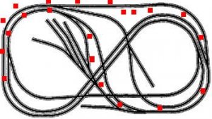
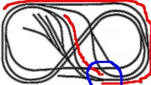
Below is a picture of my layout. I'm wondering how to attach the feeder wires to the track while maintaining separate rail polarity. Along "S" curves, the inside rail becomes the outside. How do you handle the polarity change? Assume rail A is red, B is black. After the S turn, the colors would change and then later down the line the colors won't match. Won't this cause a short? Maybe my pic will explain it better. Look at the top middle part.

View attachment 26220
Any help would be appreciated.
 

Attachments

  • 100282.JPG
    100282.JPG
    20.5 KB · Views: 228

Harold Cole

Member
Feb 15, 2006
175
0
16
69
Clayton Delaware
Yes it will cause a short,Isolate before and after each loop and make that a seperate section.You could either get a reversing unit,or if using DCC and have a booster hook it up for a reversing section or the old fashion way Double pole Double Throw Switch.
 

pgandw

Active Member
Jul 9, 2005
1,002
0
36
If you trace carefully, and you have no additions to the track plan "Granite Gorge and Northern" from the Atlas series, you will find there are no reversing sections. The track plan was deliberately designed that way. The layout is designed for the 2 figure 8s to be operated in opposite directions. The apparent "reversing sections" are actually crossovers from one figure 8 to the other which put the train in the right direction on each figure 8. Try as you might, you cannot reroute the trains to get them to run in the opposite direction on the same figure 8; doesn't matter which direction you start in.

What I'm saying can be changed by adding normal crossovers between the 2 figure 8s. Then you will have reversing loops. But unmodified, the track plan has no reversing loops.

yours in wiring
 

Harold Cole

Member
Feb 15, 2006
175
0
16
69
Clayton Delaware
Looking at the pic,the left side inside turnout should be insulated from the track that goes to the left and travels to the Right side inside turnout (insulated at that turnout also and make it a reversing section.Also insulate the same switch on the left hand side from thr turnout where it is going straight then over to the right side outer turnout and insulate it and make it a reversing section also.I might be wrong on this,but that is just what i see on this track plan.
 
Aug 28, 2005
104
0
16
82
Northwest Indiana
Harold, I don't want to beat a dead horse but no matter which glasses I wear, the left turnout taken straight will make a complete but folded circle. If the same turnout is taken diverging it makes a crossover to the outside track. Maybe a poll could be taken. This is one heck of a track plan. Joe hamr
 

Harold Cole

Member
Feb 15, 2006
175
0
16
69
Clayton Delaware
Joe,take the inside track and follow it thru the turnout taking the turnout to the right side to the inside turnout on the right side and to me it seems to reverse the train direction to the outside track.Am i seeing this wrong¿
 
Aug 28, 2005
104
0
16
82
Northwest Indiana
Help us guys, are we seeing it differently or what ? The left turnout taken diverging is not reversing direction but transferring the train via a folded figure eight seemingly to Change the direction but continuing on to the original starting point does not . Help, Help, Helphamrhamrhamrhamr
 

Ralph

Remember...it's for fun!
Jun 18, 2002
5,134
0
36
64
St. Paul, MN
Visit site
Well, if you want another opinion, with my glasses on :) I traced all of the routes with my cursor three times and always return to my starting place heading in the original direction. I'm not seeing any reversing loops although that inner loop that twists over itself on the right side gives the impression of one.
Ralph
 

pgandw

Active Member
Jul 9, 2005
1,002
0
36
I pulled out my Atlas layout books. Their wiring diagram does not show any reversing sections except the optional turntable in the yard.

John Armstrong - designer of most of the Atlas layouts - said in a sidebar in the older editions of his book, "Track Planning for Realistic Operation", stated that there were no reversing loops to keep the wiring simpler. Adding crossovers between the 2 figure 8s would enhance operations but would have complicated the wiring with reversing loops.

Of course, if you are using DCC, the only real impact of designating reversing sections in the layout is the extra cost of the auto-reverser which will never be used as such. :) In DCC you are going to insulate both rails anyway where ever you decide to set up separate blocks or power districts.

my thoughts, your choices
 

EngineerKyle

Member
Oct 3, 2005
442
0
16
63
Troy MI
Harold,

I looked at it for about 5 minutes.... imagined some routes, and I find no reversing section. Sometimes crossovers look like turnouts and can trick us into thinking there is a reversing section, when there is none. I could be wrong. Rather than follow the polarity of a rail, I find it helpful to imagine if the nose of the loco is going clockwise, and if there is anywhere in the layout that I can route it so the nose goes counter-clockwise. I was not able to do that on this layout.

ek
 

farmer ron

Member
Jan 18, 2002
377
0
16
74
B.C., canada
Visit site
Is your track down?? Take a box car, put a piece of sticky tape on one end (this is the front) pin a piece of paper to starting point beside your track..push the box car around and if you return to the same spot with the sticky tape at the same front end, you do not have a reverse. Years ago I went to a dollar store and bought couple packages of colored push pins..one pk green the other red. Put your thumb on one rail (this the red track) your first finger on the other rail (this the green track)..work your way around the layout, every 3 to 4 feet or so (and before and after every switch) put in a colored push pin to the appropritate spot beside the rail. Once you are done or along the way you can see if you are going to have any shorts and can make adjustments..Once the layout is done this way then you can start putting in the feeder wires for the appropriate sides of the rail to maintain the correct polarity.. this can also work if you have a large enough paper copy of your layout..Ron..
 

ExtremePCs

New Member
Jan 22, 2006
29
0
6
50
Thanks for the replies everyone. I didn't mean to cause you any headaches :) For those of you who don't see any problems, where are you starting from and which direction are you heading? Clockwise? I've gone over and over it and still end up having black meet red on the same rail, either at the right upper or right lower section of the layout. I'm obviously missing sometime obvious :eek:ops:

Thanks,

Jayson
 

Harold Cole

Member
Feb 15, 2006
175
0
16
69
Clayton Delaware
I'am admitting that i may be wrong,so i did a little project.I took some bell wire and carefully stapled it to some cork as not go through the insulation,used white as "B" rail and red as "A" rail and set it up as to the track diag.Spliced the wires as to the way the turnouts are in the diag,hooked wires red to red and white to white on both tracks and hooked my spare Cheif to it and powered and it went into short circuit mode.Cut the wires from the turnout on the left side,and the short went away.
 

ExtremePCs

New Member
Jan 22, 2006
29
0
6
50
Here's where I see the most apparent problem. What am I doing wrong???? The blue circle is where I get a short every time. Now where's that 4 x 8 oval plan at... :cool: I'm going to try the colored pin idea tomorrow and see what happens. Thanks for the suggestion Ron.

View attachment 26239

Jayson
 

Attachments

  • 100283.JPG
    100283.JPG
    23.2 KB · Views: 70