Thoughts behind the planning of the JGL

Gary Pfeil

Active Member
May 7, 2001
2,510
0
36
Boonton NJ
Visit site
OK, This will probably be kind of rambling. It will also be in installments because I will be doing most of it from work at lunch time. For those who enjoy reading for the sake of reading it may be entertaining. Others may not want to waste their time!

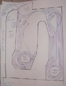
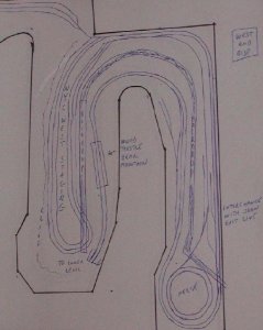
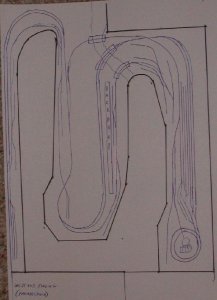
Drawings of the track plan have been roughly drawn over the last few lunch periods, and will be photographed and posted here in the next day or two. I do own Cadrail but am not willing at this time to devote the time required to learning it. In fact, I never drew actual scale plans even prior to construction of the layout. Frankly, they are not needed. I do prepare scale drawings of the layout area, then just place turnback curves of desired radius. The rest is done full size with track templates.

There are basically two questions which need to be answered prior to planning. Plan type (point to point, continuous, or something in between, like point to loop) and prototype/freelance. This assumes of course that more fundamental questions have been answered already, such as scale, era and geographical location.

Plan type: Experience building and operating layouts may well change your mind about what you originally thought you would want. I have to admit in the final analisis I never did decide, I chose both! I am more inclined to want to operate, but there is nothing that says a continuous type plan can't be operated protypically. And there are those occasions when I just want to see trains go by while I am doing something else. So all my plans have provided for continuous running. And the smallest of them still allowed way freight switching. One other thought here: Broadly speaking there are two benchwork styles, linear and "bowl of spaghetti", as I've seen it refered to in MRR. I have been a fan of linear plans for 30 years now, the main drawback being the lack of deep scenes. On the JGL, I have managed to eliminate that drawback, as I will talk about later. The main drawback of the sgetti schemes are the same train appearing in a scene more than once. This in itself wouldn't be so bad if done properly, but the image most often projected in magazine articles of the 60's when this type of plan was prevalent was one a train going one way on a lower level track, then coming back the other way a few inches higher and a few inches behind the first. Then often going back the first direction again still higher and further back still. This is what led to the idea of linear plans(that and the development of walkaround throttles!) I will talk a bit about prototype/freelance in my next post, I have to go now.

Gary
 

Gary Pfeil

Active Member
May 7, 2001
2,510
0
36
Boonton NJ
Visit site
Should I model a prototype or freelance? I agonized over this for a few years back in the early 70's. I wanted to be a "serious model railroader" but couldn't choose a prototype. My problem was I liked equipment from so many different railroads and I didn't want to not be able to have things I liked. I considered freelancing but again, to be a "real" modeler, a freelance line would have to have a loco roster painted in at most two schemes to maintain a family look. I eventually decided being a "real" modeler was a crock and decided freelance was the way to go, and I would do anything I damn well pleased. This ought to have been easier, but I had wanted to be taken seriously and frankly was paying to much attention to what others in the hobby press were saying. Funny too, because I never really cared what others think in other more important aspects of my life.
Having decided to freelance, I went about choosing a name. I wanted something which would let people know the location of the road was North Jersey. Everything I came up with sounded bad to me. To this day I can't seem to come up with names for towns and industries. On a vacation I read the novel Atlas Shrugged. This isn't the place to go into it, but I recommend this book to all you avid readers. One of the main characters is the operating vice president of Taggart Transcontinental, with headquarters in NYC, with a giant underground passenger terminal beneath their skyscrapper building. AS industries in the east close and traffic declines, the vp decides to build a contoversial branch in Colorado, and names it the John Galt Line, a phrase in the book which is central to the story. The question "Who is John Galt" in the novel is meant to convey a feeling of hopelessness, that there are no answers. It is this feeling which the vp wants to vanquish, she wants to prove that when rational decisions are made that there is nothing that can't be done. One day it dawned on me to use this name for my railroad. I know it is a poor name as it doesn't sound railroadey, but it makes sense to me. Of course I had to move it to New Jersey.
My intention was (is) to paint locos any prototype scheme I like, but to substitute John Galt Line for the name. For instance, someday I will have F units painted in B&O blue and grey, lettered JGL.
I still feel drawn to modeling a prototype, and I eventually chose the NYC. The biggest reason is the beautiful scenery in the Hudson valley. And a four track line along the river. Gorgeous steam locos and attractive diesels in lightning stripes helped make the decision.
So I was to have two roads on my layout. I elected to have the NYC be the continuous portion of the layout and the JGL be the point to point road. The JGL would have a lot of industy to switch and a long enough main to run trains from west end staging to a yard at the east end, where engine changes would be made and setouts for the modeled industries would be made as well. There would be two distinct industrial areas, served by locals out of the yard.
As for the NYC, operations would mainly consist of running passenger trains in and out of GCT on a schedule from 1950. The continuous plan of the NYC uses staging at the return loops at each end of mostly double track main. GCT is one loop, the other has yet to be defined, perhaps Albany. It is hidden so it doesn't really matter. Therr would be two dispatchers, one for the east end and one for the west end. They will each control their respective staging yard and be responsible for getting the correct train out on schedule. Using DCC, they would simply select the loco, get it going, then dispatch it to the system. Wearing a dedicated phone headset, they would communicate the comings and goings. The dispatched trains keep moving at their preset speed until the dispatcher at the other end takes control of it. A much condensed version of the 60th street yards will add freight traffic to the mix, and the interchange with the JGL will do the same on the west end.
I am going to post my very crude drawings of the track plan now. I am sorry they are so bad. Can you tell I drew them in my car while eating lunch? They will give you an idea of what I've talked about here. I will come back in afew days and talk more about specific operations I plan.
This fist page is the bottommost level. The right side is the GCT staging. The innermost tracks with the loop at the top of the right side is staging for the JGL east end, 3" above the NYV staging and reached via the helix, it is not connected to the NYC trackage. The GCT trackage becomes visable at Spuyten Dyvil, where tracks cross on a swing bridge to reach the 60th street yards in Manhatten. then four tracks follow the Hudson till they go into tunnels, do one lap on a helix to gain elevation(can't have visable grads on the waterlevel route!) The tracks then continue on the next drawing.
 

Attachments

  • p1010110.jpg
    p1010110.jpg
    96.8 KB · Views: 457

Gary Pfeil

Active Member
May 7, 2001
2,510
0
36
Boonton NJ
Visit site
This page is the rest of the NYC, the right hand peninsula is 7" above GCT staging. The left side of this peninsula is not yet definatly determined, but I would like to model the GM plant in Tarrytown. I haven't been able to locate photos, if anyone knows of any, please let me know. The right side of the peninsula is the interchange with the JGL, via the helix. The other visable scene is from the West Shore line at Bear Mountain. I decided to model scenes I liked regardless of the fact it was on the other side of the river! The west end staging is on the center peninsula and is over the one turn helix mentioned earlier. It is kept back from the edge of the aisle to the left so as to not interfere with the four tracks along the Hudson just below it.
 

Attachments

  • p1010111.jpg
    p1010111.jpg
    99.5 KB · Views: 450

Gary Pfeil

Active Member
May 7, 2001
2,510
0
36
Boonton NJ
Visit site
This last drawing is the JGL on the top level, averaging 14 to 16" above the NYC. I will talk more about this level some other time.
 

Attachments

  • p1010112.jpg
    p1010112.jpg
    92.2 KB · Views: 437

shamus

Registered Member
Dec 17, 2000
3,489
0
36
87
UK
Hi Gray,Thats one hell of a track plan you have drawn out, Wow I have always liked the idea of freelance because it gives you plenty of scope to run just what you want to.
I like also the idea of a wood trestle on Bear Mountain, that will make a special impact for viewers to look at. Have fun with this, after all, thats what this hobby is all about.
Shamus
 

marty w.

Member
Jun 11, 2002
546
0
16
Bloomington, IN
Visit site
Originally posted by Gary Pfeil
OK, This will probably be kind of rambling. It will also be in installments because I will be doing most of it from work at lunch time. For those who enjoy reading for the sake of reading it may be entertaining. Others may not want to waste their time!

Gary-
Keep going. I am finding this to be very interesting on the how and why of your planning.
Marty
 

jon-monon

Active Member
Aug 15, 2002
4,590
0
36
59
Cobblers Knob, IN
www.2guyzandsumtrains.com
Yah! Rock on Gary. I'm enjoying "seeing" your thought process. It may help you to go back and read it a few days after you write it, too. Not to mention the value of other's opinions, which is even better when they understand where you come from. I am free lance in a most free way. I'm going to model the 50's, with diesel, steam, gas elect. and logging and/or NG and/or NG type industries. I'm keepin' my SW-1500 even though it's too new. I like it. P-K was ahead of it's time :D Yah, they invented it, EMD stole it, yah thats the ticket. So NAH! :D :D :D

I must say, I do respect those who do all the research and get all those exacting details just rat!
 

Gary Pfeil

Active Member
May 7, 2001
2,510
0
36
Boonton NJ
Visit site
A quick word about deep scenes on a linear plan: If you look at the plan for the JGL, the last one posted, you will see that the backdrop which is to the left of the center aisle does not continue around the on a curve to match the aisle, but just ends. My original plan was to have it continue around and down the right side peninsula, as on the lower level. This gives more linear footage to a mainline. It dawned on me while in the early construction faze of the lower level that by keeping it short I could still have its benefit of seperating the left peninsula into two scenes (and hide lolly columns) but not have the problem of having to paint the continuation of a river on the backdrop. You see three bridges over a river in the drawing? originally, just the front bridge was there, with the river going into the backdrop, just inches behind a curved wooden trestle. It was while trying to figure how to make this look decent that I realized I could just eliminate the backdrop. The end of the backdrop near the bridge will have a 4 story building wrap around it, the other end may just be concealed with trees. When standing at the end of the center aisle, you will see the wood trestle, a concrete road bridge, a deck girder carrying the main line, and another wood trestle beyond, and be able to see clear across to the upper left hand corner of the drawing. I will post a photo of this area in its currant incomplete state to make this clear.
Also, the depth of the scene from the left aisle looking to the right is 5 feet, with the main with passing siding along the back drop having its turnouts placed within reach of the aisles, I hope to have no derailments which I can't get to within reach there, but if that does happen, the scenery in that area will be able to be lifted out from below, although I would need someone to hand it to in the aisle.
Must get back to work, more later.

Gary
 

Gary Pfeil

Active Member
May 7, 2001
2,510
0
36
Boonton NJ
Visit site
Jon, I had nearly the same thought process, or rationilazation, about the JGL being ahead of its time. In fact the decals I had made, of which I have only used some logos for a handful of cars i decalled, include the phrase "AHEAD OF OUR TIME' in script on an angle, much like the Burlingtons "EVERYWHERE WEST" It will appear on the side of locos such as Century 624's which, by the way. the JGL designed for Alco way back in the early 50's, Alco just wasn't smart enough to produce it till years later!

Gary
 

sumpter250

multiscale modelbuilder
Jan 19, 2002
3,073
0
36
80
Vernon Hills, Illinois
Visit site
Gary,
Interesting reading, some of this I've heard already, but it's still interesting reading.
This is a large basement layout, and the trackwork is mostly done. The evening I was there, four of us were operating, and there were trains running all evening. I had a thirty+ car train with a Y3, on the head end, and another, actively pushing on the rear, and, on a couple of the straight runs, was able to strech the whole thing out. It probably didn't happen in the prototype world, but on that evening, the sound of a N&W whistle was heard echoing along the Hudson river, and it sounded great!
Pete
 

Gary Pfeil

Active Member
May 7, 2001
2,510
0
36
Boonton NJ
Visit site
Earlier, I had stated a preferance for linear plans and mentioned that their shortcoming was lack of depth. Then i spoke about how I eliminated the backdrop to achieve depth. While no one has said it, some of you might have thought that what I have posted is not a linear plan. Linear plans allow an operator to follow his train around without having to run to the other end of an aisle to catch up to his train. they don't go thru walls into another aisle and such. OK, thats correct. My original plan had the track coming out of the yard making a 30" radius turn (my minimum) and coming down the peninsuls to the left of the center aisle. I wasn't too thrilled with this as i wanted to break up that 30' curve. It would appear to model like, I wanted the appearance of spaciousness. At the same time, I was thinking I could add a wye coming out of the yard, to simulate two routes. I decided against the wye, as all it would have done was eliminate the need for the trackage down the peninsula. However, running the main down the backside of the backdrop gave me the scenic look i was looking for, and freed up the other side of the peninsula for a branchline. And I knew just what I wanted to model there, the town of Garfield N.J., where the Erie's Dundee branch ran down the middle of Monroe St, crossed the Passiac River on a curved wooden trestle into Passiac. Or Clifton.
My dilemma was how was I going to operate the line? Engineers were supposed to bring their trains (which originate in Philly, the west end staging in the next room) thru the towns of Stockton and East Stockton and another town now deleted, into the yard. If the tracks went down along the backdrop on the backside, where was the engineer going to be? Standing at the end of the penisula watching as his hack went by and went away from him? At that point in time his loco would be about to enter the yard. And it would be at the other end of the basement! Or would he start walking to the other end of the basement as his loco went by him, ready to catch sight of it as he stood near the bomb shelter door? (The bomb shelter door is the reason for the aisle at the top of the plan) The answer was simple and preserved, to my way of thinking, the integrity of a linear plan. A dwarf signal is mounted between the siding tracks, facing down the length of the peninsula. Its aspect is controlled by the throw of the turnout at the yard end of the siding. This turnout is controlled at the yard panel. The yard master controls access to the yard by keeping the turnout thrown for the siding track used for west bound departures. ( The siding uses right hand running) So, an engineer running from Philly to the yard brings his train into the siding tack and runs up to the signal. He is physically standing at the end of the peninsula. he can see the red or green aspect of the signal, and acts accordingly. the yard master throws the turnout when he is ready for the train, and the engineer then walks over to the yard area and brings in his train. This is just an example of how one decision daisy chains into others.

Gary
 

Hoghead

Member
Jul 10, 2002
177
0
16
57
Eastern US
Visit site
Freelance names with a Jersey flair?

Jersey Northwestern RR (Hoboken-Suffern NY-Buffalo)
Hoboken and Harrimus
Raritan & Rancocas
P&H (Passiac and Harrimus...actual shared assets line that runs from around Oak Island to Hack)
Burlington-Bordentown & Boundbrook
Raritan Valley Western
Camden and Cape May
Atlantic City Seashore
Hackensack River Line


Maybe I can think of few more later
 

Gary Pfeil

Active Member
May 7, 2001
2,510
0
36
Boonton NJ
Visit site
Hoghead, Thanks for the suggestions but John Galt Line it is! When Pete visited, the only upper level trackage in place was the yard on the right peninsula. Some isolated track was in place on the other side of the backdrop, and all ties for the handlaid sections were in. I have just finished that part and have run the first trains. I have taken a few photos to commemorate the event. I hope T sees this, I just told him to not worry about in progress photos! This photo shows the wide part of the peninsula to the left of the backdrop in the drawing. You can see I have a lot to do! An EL local is going down the Dundee, I mean Garfield branch. It has just come off the main and is bringing the first two cars down the line. And the first car is the Cindy Harbor car Pete so generously sent.
 

Attachments

  • p1010119.jpg
    p1010119.jpg
    99.8 KB · Views: 360

Gary Pfeil

Active Member
May 7, 2001
2,510
0
36
Boonton NJ
Visit site
Pete, Wanted you to see this. This is the turnout with the superelevation on the diverging route which is the main, with the other lead being the entry to the Garfield branch. I'm happy to report smooth running thru here, and no cars have tipped over yet! I won't try doublestacks till I install safety netting per your advise!
 

Attachments

  • p1010114.jpg
    p1010114.jpg
    96.4 KB · Views: 337

sumpter250

multiscale modelbuilder
Jan 19, 2002
3,073
0
36
80
Vernon Hills, Illinois
Visit site
Gary,
Good lookin turnout !, You really didn't have to dress it up with the suzieQ locos, but they do add that certain something.
I'm honored to have that boxcar one of the first down the Garfield branch. Thanks.
Pete
 

Gary Pfeil

Active Member
May 7, 2001
2,510
0
36
Boonton NJ
Visit site
I'm back to talk a little about the operations I had envisioned for the JGL. I wonder if any of you do as I do and sit staring at your proposed track plan, running trains over it in your mind? I know some of the programs for trackplanning allow you to actually run trains on them, but I've been doing it in my head for a long time. I don't know how else one can tell if the design will allow the operation it takes to maintain interest. Anyway, my JGL runs from Philly to Boston. It is a branch of a transcontinental railroad, Taggart Transcontinental. Now, TT runs from NYC to somewhere in Ca., take your pick. The two major roads with NYC as a terminal ate NYC and Pennsy. Since I am modeling the NYC as well, TT had to become the Pennsy. So, it runs from Penn Station across NJ to Philly and on. Wanting to serve Boston and not duplicate service offferd by the New Haven, it built the JGL. Running northeast from Philly, it goes thru the industrial portions of NJ prior to entering New York state, then crossing the Hudson (in a tunnel!) and on across to Boston. The modeled portion of the JGL is, in real life, the Paterson area. I created fictional towns to allow a little of this and a little of that. In real life, several small railroads operating thru northern Jersey utilized Maybrook yard, owned by the New Haven. It was a way of accessing New England. Well, the JGL yard is located in somewhat the same geographical location. Unfortunately, only 1/2 scale mile of track seprates it from the Paterson area, but such are the compromises we have to deal with in modeling. The thing that appeals to me about Maybrook was the variety of motive power to be found there. NH, L&HR, L&NE, Erie, NYC. So my JGL yard serves a similar purpose. Located west of the Hudson, and seeing as the Hudson is crossed via a tunnel, the JGL is a dieselized road east of the yard. Steam still runs to its west. All motive power is changed here,as well as hacks. Also, power from roads such as NYC, Erie, B&M, and Rutland can appear there on transfer runs, out of hidden staging. The yard is primarily a division point, serving to allow crew changes. It does little classification, but does originate a couple locals for the industries in Jersey. This idea forms the crux of operations on the JGL. Steam powered trains from Philly arrive at the yard, the power goes to the engine facilities(yet to be built but firmly pictured in my mind!). Cars are setout and added as appropriate, diesels are put on, and the train goes dwon the helix to staging. This works well as the radius of the helix won't permit some of my larger brass to use it. But thats not the reason, of course, its the tunnel which has a poor ventalation system and precludes use of steam. Likewise, diesels returning from the helix (Boston) change to steam at the yard (as yet unnamed) The transfers from the other roads(except NYC) simply run to the yard, layover and go back to staging. The NYC trains actually have somewhere to go(the lower level of course). One exception to the engine change will be the premier passenger train, the Comet, which will be powered by stainless steel E6's which will run thru. With the completion of the main on the bigger peninsula, along with the section of the Garfield branch which leaves the yard, crosses the river on a wood trestle and, in actuality, joins the main headed back for the yard(in my imagination this part of the main when used for the Garfield branch is not the main at all, but trackage rights over another roads main to reach the remainder of the Garfield branch) I am able now to perform out and back runs from the yard. Once the main is completed down the far left side of the plan and on into the next room for staging(Philly) I will be able to operate the way I planned. For now, I can get a taste of what will be, and during the first oprating session utilizing the new trackage last night, one of my visions came true. A coal drag of empties out of NYC, hauled by a pair of geeps, ran to the interchange with theJGL. Taking siding there, the crew waited for clearance from the dispatcher, then ran around their train, and proceeded to haul it hack first up the interchange (on JGL trackage rights) to the yard. Cutting off the string of hoppers, the NYC units and hack were directed to a siding to wait, while a yard switcher attached a JGl hack, and a mikado coupled up to the head end. getting clearance to leave the yard, the train headed west on the main, going thru Stockton, the scene from my photo contest entry. It had been a long time in the making (5 years from conception) but well worth the wait. Now when I finish the industrial area I can send out those locals...oh boy!

Gary
 

Bob Collins

Active Member
Feb 1, 2001
928
0
36
88
Council Bluffs, IA
Visit site
Hi Gary;

Even with all of this great conversation about layouts and operations, I am interested in walls:D

In the photos I can see landscaped walls in the background. How far are those walls from the edge of the layout?

In my haste or zeal, or both, I built my layout as a walk around without giving any thought at all about trying to tie the walls in with scenery or painted sky or something of that variety. One wall is only about 24" from the edge, but the other one is closer to five feet:eek: :eek:

I have even given some thought, although not a whole lot yet, to adding on another 2 to 3 feet to bring the edge closer to the wall and, of course, at the same time offer myself another 3' X 22' to "create" something marvelous:rolleyes: :rolleyes: That would still allow me to walk around although I also need to consider how much operating I want to do from that side. That may only impact whether to go 2 or 3 feet wider.

Bob