

In regard to the brass wire flexing, perhaps a telescoping steel tube can be slid over the wire prior to soldering on the bottom bar. If it were a tight fit it ought to eliminate the flexing.
stub switch or turnout
- Thread starter jim currie
- Start date
You are using an out of date browser. It may not display this or other websites correctly.
You should upgrade or use an alternative browser.
You should upgrade or use an alternative browser.
Bill:
what size rail are you using? You might find that it's stiff enough to hold gauge for the few inches you need.
what size rail are you using? You might find that it's stiff enough to hold gauge for the few inches you need.
David,
Yes, I think you're right --- no matter the rail size. But it would be nice to have something that looks like the prototype bars. I guess small diameter plastic rods cemented in place might work.
Gary,
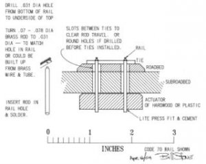
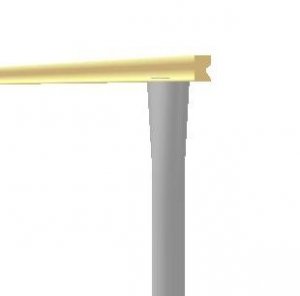
Here is my thinking (see sketch)
The diameter of the "rod" was selected to more or less match the base of the rail. The smaller portion dia --- and the hole in the rail --- to match the width of the rail head. I doubt if any of it would show that much.
I suspect the hardwood (my preference) or plastic block on the under side would have a few advantages over the pc tie idea. 1] it would be easier to install than getting down there and soldering upside down. 2] it would eliminate the worry about pivoting & breaking the joints. And 3] would give one something to easily attach the actuating mechanism to --- like a screw in the side or bottom of it.
Please note --- I've not tried this yet. It's just thinking on paper (which I hope is reasonably clear.)
BillS
Yes, I think you're right --- no matter the rail size. But it would be nice to have something that looks like the prototype bars. I guess small diameter plastic rods cemented in place might work.
Gary,
Here is my thinking (see sketch)
The diameter of the "rod" was selected to more or less match the base of the rail. The smaller portion dia --- and the hole in the rail --- to match the width of the rail head. I doubt if any of it would show that much.
I suspect the hardwood (my preference) or plastic block on the under side would have a few advantages over the pc tie idea. 1] it would be easier to install than getting down there and soldering upside down. 2] it would eliminate the worry about pivoting & breaking the joints. And 3] would give one something to easily attach the actuating mechanism to --- like a screw in the side or bottom of it.
Please note --- I've not tried this yet. It's just thinking on paper (which I hope is reasonably clear.)
BillS
Attachments
Hi Bill, hey, nice drawing! You know, it's funny how certain things just may not occur to you until someone else says something to jar you. I hadn't considered any way of attaching the throw wire to the bar below other than solder. Now, your idea of a press fit and cement got me thinking. I am not mechanically inclined, so please forgive me if I say something stupid, or unworkable. My first thought was what kind of cement would be used and I suppose 5 minute epoxy? Then I thought the problem would be not being able to disassemble for point service. I've learned over the years that being able to take things apart even when you see no reason why you'll want to do so is a good idea. When you wrote about turning down the wire to solder the tip in the rail, my first thought was " I can't turn it down, I have no such equipment or knowledge" Later, I thought that if you are going to turn something down, why not use a small diameter brass threaded rod? solder to the rail the same way, but use nuts to fasten to the rod below. To avoid turning down the threaded rod, perhaps a hole could be drilled in its end, and a very short piece of .031 wire soldered in.
In my original thinking, I was going to try the largest wire that could be accomodated in the rail and check its performance. Of course I hoped it would work fine , end of problem. If it flexed too much, I hoped there would be telescoping brass rod available. Then I could solder the wire to the rod, and the rod would not flex. Come to think of it, if brass rod could be used, the bottom end could be threaded and a screw driven in, preventing the throwbar from falling off. The lighter the throwbar the better, because its weight will be hanging on the solder joint of wire to rail. It's pretty much a matter of seeing what size wires and rod are available, I haven't checked.
In my original thinking, I was going to try the largest wire that could be accomodated in the rail and check its performance. Of course I hoped it would work fine , end of problem. If it flexed too much, I hoped there would be telescoping brass rod available. Then I could solder the wire to the rod, and the rod would not flex. Come to think of it, if brass rod could be used, the bottom end could be threaded and a screw driven in, preventing the throwbar from falling off. The lighter the throwbar the better, because its weight will be hanging on the solder joint of wire to rail. It's pretty much a matter of seeing what size wires and rod are available, I haven't checked.
Point well taken, Gary. The cement does rather make everything fixed for all time. One could unsolder the rods from the rail, but that certainly is not be the best solution.
I wonder if the answer might not be to drill and tap cross holes in the hardwood/plastic actuator so that set screws could retain the rods in the actuator. These could be relatively large diameter screws so the threads would be nice and coarse to grip the wood or plastic. Very likely set screws would make initial assembly easier anyway..... Goes to show --- two (or more) heads really are better than one.
Actually, I think the wire-in-tube apprach would be easier than turning down rod --- even if one does own a lathe. Your threaded rod approach would work too, but it wouldn't be much fun drilling a hole in the end of the rod, and as it would take 4 nuts per turnout to retain the threaded rods, the wire-in-tube is probably the less expensive, most straight forward approach.
BillS
Just my 2¢ worth.
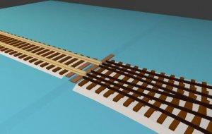
I dug around in my old (1976 vintage) photos and came up with the attached pic - unfortunately it is the only one that shows one of my stub turnouts - and it is not too sharp. This is H0n3 with code 55 rail profile.
(The whole trackwork wasn't not quite finished at this time, as you can see from the clearly unfinished crossing in the background and the missing .)
The moving approach rails are held in gauge by a PC-board tie which I sawed out of abreadboard (hence the holes in it). The first spikes which fixed these rails to the ties were still out of the bottom of the picture, about 3 cm away from the points of the moveable rails.
I remember well that the force needed to bend the rails is amazingly small. Therefore I installed an actuating lever along the track center (0.8 mm hard brass wire, about 1/32"). It was threaded down through the road bed through a fitting brass tube. Below the subroadbed I attached a lever with about twice the length of the crank between the turnout, and from there I went on with a spring-loaded choke cable to the layout edge.
The actuating lever had the double function of moving the points and at the same time pressing the rails down onto the ties. So the lifting of the rails never was a problem.
The turnout worked fine, however I tore down this experimental layout after only a few months of use. Hope this pic helps also a bit.
Ron
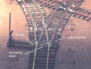
I dug around in my old (1976 vintage) photos and came up with the attached pic - unfortunately it is the only one that shows one of my stub turnouts - and it is not too sharp.
This is H0n3 with code 55 rail profile.(The whole trackwork wasn't not quite finished at this time, as you can see from the clearly unfinished crossing in the background and the missing .)
The moving approach rails are held in gauge by a PC-board tie which I sawed out of abreadboard (hence the holes in it). The first spikes which fixed these rails to the ties were still out of the bottom of the picture, about 3 cm away from the points of the moveable rails.
I remember well that the force needed to bend the rails is amazingly small. Therefore I installed an actuating lever along the track center (0.8 mm hard brass wire, about 1/32"). It was threaded down through the road bed through a fitting brass tube. Below the subroadbed I attached a lever with about twice the length of the crank between the turnout, and from there I went on with a spring-loaded choke cable to the layout edge.
The actuating lever had the double function of moving the points and at the same time pressing the rails down onto the ties. So the lifting of the rails never was a problem.
The turnout worked fine, however I tore down this experimental layout after only a few months of use. Hope this pic helps also a bit.
Ron
Attachments
pic
Just thought id post the prototype pic i took at Allaire State park in Wall Township, NJ. This is a 3-foot guage 3 way stub.
Click here
Hope you guys like it!
Chris
Just thought id post the prototype pic i took at Allaire State park in Wall Township, NJ. This is a 3-foot guage 3 way stub.
Click here
Hope you guys like it!
Chris
The clown had a think
Hi guys,
I have been very interested in this thread, as I am currently building my first turnouts. I too, would like to build a stub switch at some point and so the problems intrigue me. I think I have solved most of them, so please read through to the end and maybe you will pick up an idea or two.
The first problem is getting a good joint from the control rod to the rails. This would be done like this.
First of all I would use 1/8 steel wire rod. I get my rods from Home Depo. They are used to hang false ceilings and come in 8 or 10 foot lengths for about 99 cents. This is good stuff as it is stiff, straight and has a galvanized coating. The galvanized coating is very thin and can be sanded off or knocked off with a mill file quite with little effort so it will take to the solder.
Take a piece of wire about 3" long and flatten one end with a hammer on an anvil.
Attachments
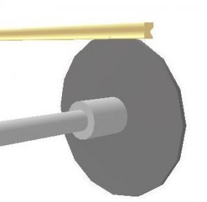
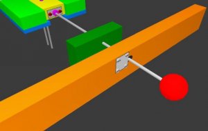
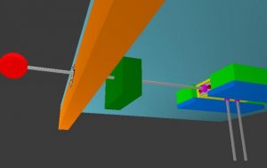
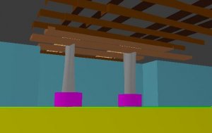
Now the rods need to pivot slightly so drill 2 holed in a piece of 1"x2"x3" wood. The holes should be centered on the centers of the rails. The height of the rails is determined by collar washers. Collar Washers are sold at the LHS for use with model air plains and come in a variety of sizes. They have a set screw in the side to lock the washer on to a rod, like say, hold a wheel on the axle of the plain. They come with a little hex key to fit the set screw and are way more strong than we need for this aspirations. The collar washers in my pix are purple.
Attachments
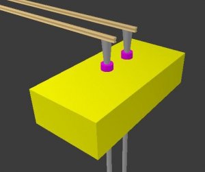
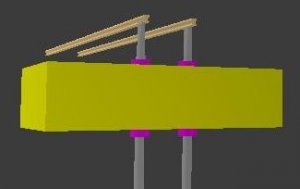
The yellow control block is held in place and guided by four other blocks, like a mini drawer. A collar washer can be used to attache the main control rod by soldering the collar washer to a piece of tin and then screwing the tin to the end of the control block. This way the main control rod could be removed and rep;aced easy. Candle wax would make the wood slide better.
Attachments
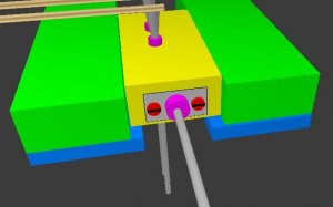
The control rod would pass through a guide block (green) and then through an oval hole in the facile board. On the facia would be a piece of tin with 4 screws in it to make it secure. The rod would have three cuts in it that would correspond with the alignment of the tracks. Simply move the knob to the right and slide it until the tin caught on the next cut.
Attachments
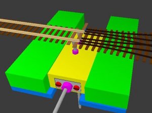
AFTERTHOUGHT: A brass tube could be slid over the main control rod and the brass could have the cuts in it. This way you could keep making them until you had it just right and you would not weaken the main rod by putting cuts in it. The brass tube could be soldered to the main rod once you were happy with it.
What do you think of my ideas?
TrainClown
What do you think of my ideas?
TrainClown