SPACE: 1999 MARK IX HAWK

bgt01

Exemplary Confidant
Jan 26, 2012
576
843
93
Ohio
FUSELAGE

This is the main fuselage that connects to the rear of the command module. It got a complete repaint. Through studying the model I discovered the proportions of this part are off by being too narrow in the center. Changing that would have lead to a host of changes I wasn’t ready to try and undertake, so I settled for working within the dimensions of the part as-is, which is fine overall. Again, all the tabs were cut off and new ones glued from behind.
 

Attachments

  • MAIN FUSELAGE_1.jpg
    MAIN FUSELAGE_1.jpg
    220.7 KB · Views: 25
  • MAIN FUSELAGE_2.jpg
    MAIN FUSELAGE_2.jpg
    46.5 KB · Views: 21
  • MAIN FUSELAGE_3.jpg
    MAIN FUSELAGE_3.jpg
    55.2 KB · Views: 21
Last edited:

bgt01

Exemplary Confidant
Jan 26, 2012
576
843
93
Ohio
Repainting the part had to be approached as 2 parts. Like most of the Hawk, the port and starboard sides are not mirror images of each other due to the last-minute freehand nature of detailing the model. So each side was done separately with little part crossover. I added panels, lines, markings and raised details as best I could. Again, I took some design liberties with the drawn on parts and made some as raised detail to add more realism. I couldn’t find out what the gray square with the big “E” said on it, so I made it up and wrote “Earth Global Defence Command, Hawk Mk. 9 013.” The “013” was for my birthday:). There are 4 squares at the rear that should have raised small raised circles. They were too small for me to make, so I used the same metal pick technique I used on the wing edges in reverse. I poked a tiny hole in the center then slowly pushed the pick through from the back. This pushed the paper out into a raised circle. I also did this with the raised circle on the top.
 

Attachments

  • d1.JPG
    d1.JPG
    348.9 KB · Views: 14
  • d2.JPG
    d2.JPG
    334.6 KB · Views: 16
  • d3.JPG
    d3.JPG
    161.1 KB · Views: 14
  • d4.JPG
    d4.JPG
    344.5 KB · Views: 14
  • d5.JPG
    d5.JPG
    241.2 KB · Views: 14
  • d6.JPG
    d6.JPG
    276.5 KB · Views: 14
  • d7.JPG
    d7.JPG
    342 KB · Views: 14
  • d8.JPG
    d8.JPG
    337.8 KB · Views: 14
  • d9.JPG
    d9.JPG
    409.8 KB · Views: 15

bgt01

Exemplary Confidant
Jan 26, 2012
576
843
93
Ohio
The top was the hardest part because the tube cage on the model restricts getting a good look at it, but it seems rather plain. There are more greeblie parts I’ll have to try and make, but I’m holding off on that until I get to the tubing.

I also added the four small trapezoid “wings” at the front and rear at each side. I drew them out on 67 lb. white cover and glued them on with Super Glue gel.

By far the most difficult part has been the geometric trim pieces that go across the top of the squares. This part is very small and thin. I used a new X-acto blade and used no pressure when cutting. I just moved the blade back and forth until the part was finally cut. I managed to not tear, crease or otherwise mangle it this way. The port side is done, but I still have to do the starboard one.
 

Attachments

  • d10.JPG
    d10.JPG
    250 KB · Views: 17
  • d11.JPG
    d11.JPG
    411 KB · Views: 17
  • d12.JPG
    d12.JPG
    416.6 KB · Views: 17
  • d13.JPG
    d13.JPG
    321.4 KB · Views: 18
  • d14.JPG
    d14.JPG
    423.1 KB · Views: 18
  • d15.JPG
    d15.JPG
    436.9 KB · Views: 17
  • d16.JPG
    d16.JPG
    431.7 KB · Views: 17

Rhaven Blaack

!!!THE MAN BEHIND THE CURTAIN!!!
Staff member
Administrator
Moderator
Jun 12, 2009
12,493
9,857
228
Oregon
www.deviantart.com
It is looks like you are off to a great start to completely redesigning this model. I like how the new parts look.
I think that after you finish, you will have a completely different model from the one that Jaybat designed.
 

Revell-Fan

Co-Administrator
Staff member
Administrator
Moderator
Aug 1, 2009
11,595
12,338
228
Vreden
It would be cool to have a direct side-by-side comparison of both versions..! :)
 
  • Like
Reactions: vipers7

bgt01

Exemplary Confidant
Jan 26, 2012
576
843
93
Ohio
REAR FUSELAGE

This part connects to the main fuselage. Along with a complete redraw, I cut the tapered end off the rear. This area is flat on the studio model and is where the main engine and a lot of greeblies are attached. Again, I cut off all the tabs and glued new ones made of printer paper from the rear. The new flat rear is just blank card stock trimmed to fit.
 

Attachments

  • REAR FUSELAGE_1.jpg
    REAR FUSELAGE_1.jpg
    78.5 KB · Views: 33
  • REAR FUSELAGE_2.jpg
    REAR FUSELAGE_2.jpg
    132.1 KB · Views: 30
  • REAR FUSELAGE_3.jpg
    REAR FUSELAGE_3.jpg
    86.2 KB · Views: 30
  • e1.JPG
    e1.JPG
    292.6 KB · Views: 28
  • e2.JPG
    e2.JPG
    373.9 KB · Views: 29
  • e3.JPG
    e3.JPG
    261.5 KB · Views: 29
  • e4.JPG
    e4.JPG
    249 KB · Views: 28

bgt01

Exemplary Confidant
Jan 26, 2012
576
843
93
Ohio
A main part to the redraw was adding lined areas at the front and rear. This simulates the “grooved” pieces on the studio model. I also added the banded areas and the hull details, most of which are drawn on but I chose to make raised. This part doesn’t have a lot of intricate detail, but it does have a small ladder section on the port side. I made this out of a single layer of card stock and it took a LOT of slow, precise cutting. It’s not perfect, but I was happy to get it this good on the first try. I made it bigger than I needed so I could trim it exactly where I needed on the hull line.
 

Attachments

  • e5.JPG
    e5.JPG
    193.6 KB · Views: 10
  • e6.JPG
    e6.JPG
    335.5 KB · Views: 11
  • e7.JPG
    e7.JPG
    308.8 KB · Views: 11
  • e8.JPG
    e8.JPG
    373.1 KB · Views: 10
  • e9.JPG
    e9.JPG
    320.2 KB · Views: 12
  • e10.JPG
    e10.JPG
    267.5 KB · Views: 11

bgt01

Exemplary Confidant
Jan 26, 2012
576
843
93
Ohio
COMMAND MODULE BOTTOM

The bottom of the command module is a sort of rounded teardrop shape with a lot of paneling. The original part had no detailing and was a good bit off on the sizing. I resized it by increasing the length by .625”. Next I cut off all the tabs on the orange section. These areas were edge glued with Super Glue gel. I kept the tabs in the white areas and at the rear as they weren’t as noticeable. Then the entire bottom was edge glued to the command module. Then I attached the nose cone. This part needs additional scoring and folding that isn’t noted on the original part in order to fit the actual shape of the hole in the front. Also, the white tabs on the nose have to be cut off and new, much smaller back tabs added to make the small triangle top piece attached to the command module fit correctly.
 

Attachments

  • BOTTOM_1.jpg
    BOTTOM_1.jpg
    77.3 KB · Views: 25
  • BOTTOM_2.jpg
    BOTTOM_2.jpg
    35.8 KB · Views: 23
  • f1.JPG
    f1.JPG
    237.3 KB · Views: 22
  • f2.JPG
    f2.JPG
    287.2 KB · Views: 22

bgt01

Exemplary Confidant
Jan 26, 2012
576
843
93
Ohio
The detailing for this part was really hard as I was working with an unfolded part. I designed the panels as flat, separate pieces and scaled the to the approximate sizes I needed. Starting at the rear, I glued the parts to the very bottom and slowly worked the panel until it folded along the hull. Then I trimmed away the excess as flush as possible to follow the join line between the bottom and command module. The two forward sections were the hardest as they angle in the most toward the nose. Those I had to cut off at the fold line, trim, and glue them on separately otherwise the angle of the fold was way off toward the rear. They aren’t perfect, but they’re pretty good for making it up on the fly.;)

The final detail was to add the nose gun. It’s the only gun seen firing on screen. On the original model this was just a small light at the end of a tube. My replication is just a piece of hard, black wire cut to length and inserted in a small hole I made with my metal pick. I carved out the hole with an X-acto just enough to get the wire to lay flat against the hull and glued it in place with a drop of Super Glue gel.
 

Attachments

  • f3.JPG
    f3.JPG
    296 KB · Views: 19
  • f4.JPG
    f4.JPG
    407.4 KB · Views: 18
  • f5.JPG
    f5.JPG
    391.3 KB · Views: 21
  • f5.JPG
    f5.JPG
    391.3 KB · Views: 19
  • f6.JPG
    f6.JPG
    375 KB · Views: 18

bgt01

Exemplary Confidant
Jan 26, 2012
576
843
93
Ohio
MAIN BODY ASSEMBLY

The 3 main body pieces are now lined up and glued together!:)
 

Attachments

  • g1.JPG
    g1.JPG
    660.7 KB · Views: 16
  • g2.JPG
    g2.JPG
    677.9 KB · Views: 17
  • g3.JPG
    g3.JPG
    325.4 KB · Views: 17
  • g4.JPG
    g4.JPG
    302.2 KB · Views: 18
  • g5.JPG
    g5.JPG
    280.1 KB · Views: 19
  • g6.JPG
    g6.JPG
    346.5 KB · Views: 17
  • g7.JPG
    g7.JPG
    375.3 KB · Views: 18
  • g8.JPG
    g8.JPG
    360 KB · Views: 17

Revell-Fan

Co-Administrator
Staff member
Administrator
Moderator
Aug 1, 2009
11,595
12,338
228
Vreden
This is looking very good. One tip regarding re-texturing and modding unfolded parts: Assemble the part as is, make the changes (new texture etc.), then cut the part back to pieces again and use this as a model to re-texture a second print of the part which will become the definite piece. ;)
 
  • Like
Reactions: Tonino and bgt01

Rhaven Blaack

!!!THE MAN BEHIND THE CURTAIN!!!
Staff member
Administrator
Moderator
Jun 12, 2009
12,493
9,857
228
Oregon
www.deviantart.com
I really like the time, effort, energy, and work that you are putting into this.
So far, you have COMPLETELY redesigned this entire model. I am really looking forward to seeing how it will turn out!!!
 
  • Like
Reactions: bgt01

bgt01

Exemplary Confidant
Jan 26, 2012
576
843
93
Ohio
Thanks guys!

WING GUNS


On to the wing guns! Again, all the details were redrawn. The middle is a simple tube with the long tab removed, remade in printer paper and glued from behind. I used a little orange marker on the tab to further hide the seam. Both ends are made onto the original part. I find that harder to work with and get a nice curl and/or a clean glue edge, so I cut both off and assembled them separately. On both ends I cut off the tabs and made 1 new tab for the side pieces. I was going to try and recess the areas on the front piece for the gun barrels, but I decided that was too small and it would likely be a lot of time spent on a part I wouldn’t like the looks of.
 

Attachments

  • WING GUNS_1.jpg
    WING GUNS_1.jpg
    81.5 KB · Views: 17
  • WING GUNS_2.jpg
    WING GUNS_2.jpg
    68.4 KB · Views: 12
  • WING GUNS_3.jpg
    WING GUNS_3.jpg
    60.3 KB · Views: 12
  • h_1.JPG
    h_1.JPG
    322.6 KB · Views: 12
  • h_2.JPG
    h_2.JPG
    306.5 KB · Views: 10
  • h_3.JPG
    h_3.JPG
    165.8 KB · Views: 12

bgt01

Exemplary Confidant
Jan 26, 2012
576
843
93
Ohio
The guns were assembled easily. The rear is supposed to have a white grooved band wrapped around it with a flat white rectangle at the seam, which is missing on the original part. I drew up the band and made it out of card stock. The rectangle is just a piece of 67 lb. white cover. On the studio model, the guns’ rear have a circular end cap with some raised detail. I drew up a version of this and glued the parts to layered 1mm chipboard to make a 2mm tall part. I edge colored this with silver Sharpie. I printed out a second set of parts, glued it to 67 lb. white cover and used a hole punch and scissors to trim out the raised ring. Both parts were glued together and I got a nice representation of the actual end piece.
 

Attachments

  • h_4.JPG
    h_4.JPG
    314.7 KB · Views: 12
  • h_5.JPG
    h_5.JPG
    333.6 KB · Views: 12
  • h_5.JPG
    h_5.JPG
    333.6 KB · Views: 11
  • h_6.JPG
    h_6.JPG
    145 KB · Views: 12
  • h_7.JPG
    h_7.JPG
    257.8 KB · Views: 11
  • h_8.JPG
    h_8.JPG
    318.5 KB · Views: 11

bgt01

Exemplary Confidant
Jan 26, 2012
576
843
93
Ohio
The final step was to make the front barrel end. On the model, this is a tube with a small notch cut out of the forward end. I made this using the barrel section from the original part. I colored the back side with silver Sharpie and cut some notches out of both sides. I curled the part, glued the seam and glued both ends on with Super Glue gel.
 

Attachments

  • h_9.JPG
    h_9.JPG
    110.8 KB · Views: 9
  • h_10.JPG
    h_10.JPG
    277.6 KB · Views: 10
  • h_11.JPG
    h_11.JPG
    267.1 KB · Views: 10

bgt01

Exemplary Confidant
Jan 26, 2012
576
843
93
Ohio
BOOSTERS

Like the other parts, the boosters got a complete repaint. Also like the other parts, these are not mirror images of each other. They are largely the same but the studio model has several hand-drawn details on each. The original part is missing almost all this detail. Most of it became raised detail, including some liberties I took with the “freehand” parts. The areas that face into the hull are somewhat covered and hard to see, but it looks like the parts are mostly plain in those areas. This would make sense because the model was rushed and studio modelers don’t often spend time detailing areas the camera won’t see.:rolleyes:
 

Attachments

  • BOOSTERS_1.jpg
    BOOSTERS_1.jpg
    160.2 KB · Views: 21
  • BOOSTERS_2.jpg
    BOOSTERS_2.jpg
    139.4 KB · Views: 18
  • BOOSTERS_3.jpg
    BOOSTERS_3.jpg
    115 KB · Views: 18
  • BOOSTERS_4.jpg
    BOOSTERS_4.jpg
    119.4 KB · Views: 19
  • i_1.JPG
    i_1.JPG
    346 KB · Views: 18

bgt01

Exemplary Confidant
Jan 26, 2012
576
843
93
Ohio
I stared by cutting off the rear cones where the exhaust mounts. I cut off the tabs, made a new one for the sides and glued it from behind. I curled and glued the sides and glued the flat ends flush. There are some tiny gaps on the ends, but I believe the exhaust will help hide this.

Next I made the forward ends. These are a little tricky because they cones with a flat section that faces outward. I cut them off the center and curled the curved areas like normal, then glued the small cut areas where the flat sections end, Next I glued the seams together using a new tab glued from behind. You really need to go slow to avoid really bad creases or misshapen bases. Also, leave the forward end open until the part is attached to the center. It gives you a good place to hold it and you can poke it in place from the inside if you need to.

Next I curled and glued the center sections, again with new tabs made from 20lb. printer paper glued from behind. Then I glued two oversize pieces of card to both ends of the center sections and cut them to size with scissors. This gave me a flat surface to edge glue both ends. Rawen’s Starfleet models use these for the bussard collectors and it works great.;)
 

Attachments

  • i_2.JPG
    i_2.JPG
    130.3 KB · Views: 12
  • i_3.JPG
    i_3.JPG
    356.1 KB · Views: 11
  • i_4.JPG
    i_4.JPG
    330.9 KB · Views: 11
  • i_5.JPG
    i_5.JPG
    388.5 KB · Views: 12

bgt01

Exemplary Confidant
Jan 26, 2012
576
843
93
Ohio
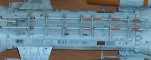
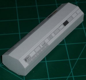
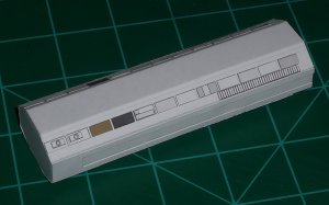
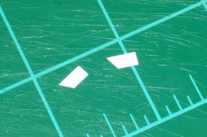
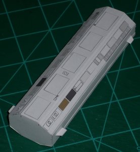
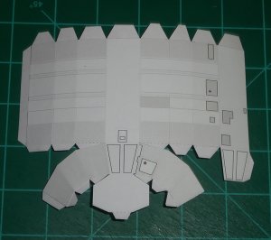
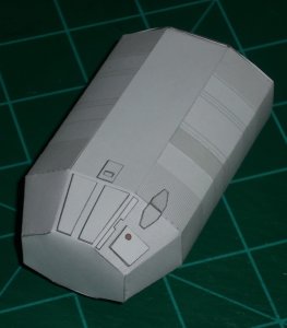
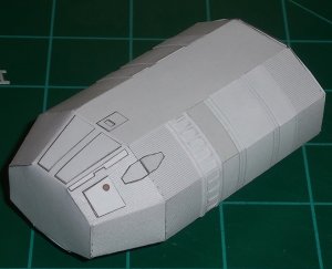
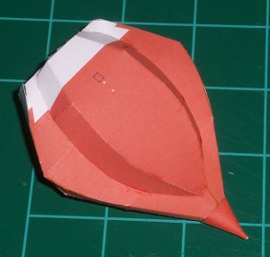
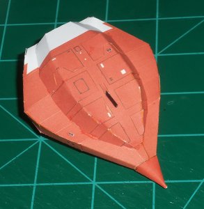
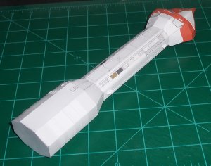
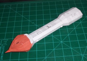
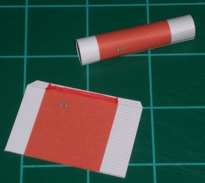
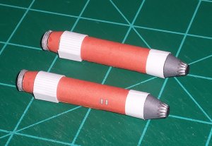
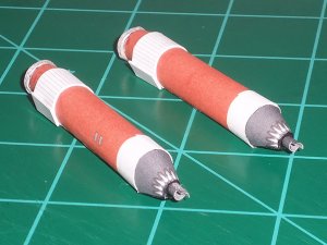
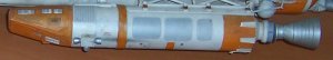
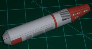
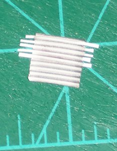
Next up was adding the raised details. This was straightforward with a few exceptions. For the small orange stripes I made some that were longer than needed. I glued one end toward the top where you can see it then wrapped it around to where it ended at the seam. The longer piece let me trim the stripe exactly where I needed it instead of winding up short like printing a copy of the part would have done.

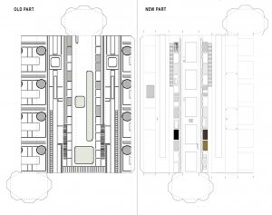
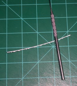
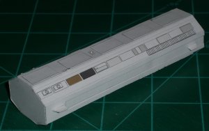
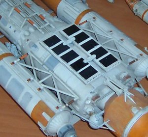
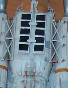
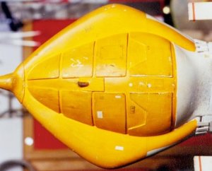
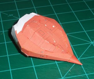
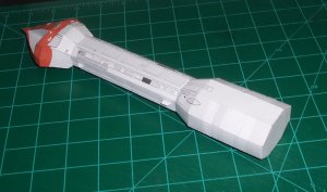
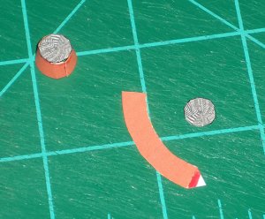
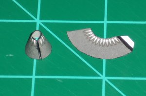
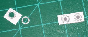
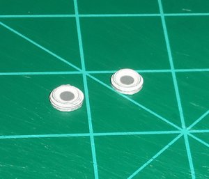
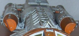
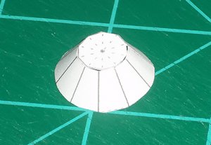
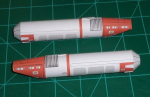
On the studio model the gray section on the top is rather thick and looks sort of like a vent. I think it’s ribbed plastic. For this, I glued a copy of my part, which I redrew using gradient for shading, to 1mm chipboard and edge colored it with silver Sharpie. Then, I cut another copy into strips and glued them in place, matching the texture. This gives it a raised look somewhat like the studio part. I trimmed the excess off the edges, curled it and glued it into place.

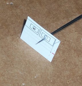
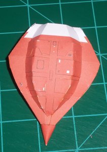
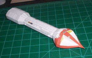
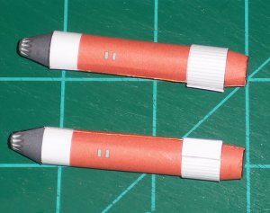
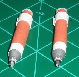
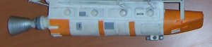
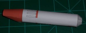
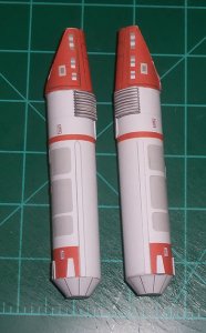
The studio model has some small signage at both ends that can’t be read. Since most of the stickers on the studio model are from the Airfix Harrier kit they probably say something about “jet blast.” Since they are near the exhaust and where the maneuvering thruster goes I went with that and made some that say, “DANGER. JET BLAST. STAND CLEAR.” Ironically, at this size you can’t read mine either! But I know they are there.:)

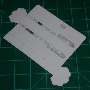
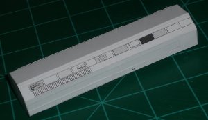
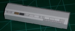
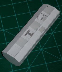
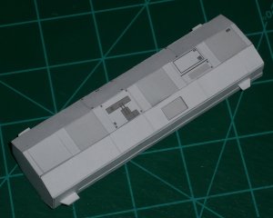
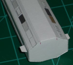
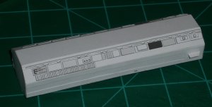
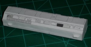
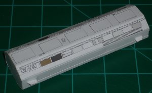
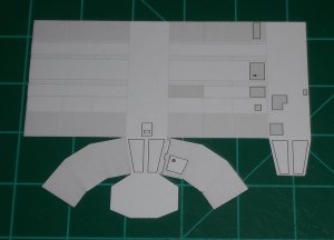
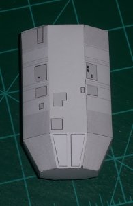
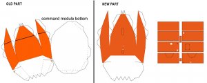
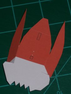
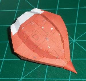
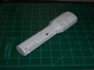
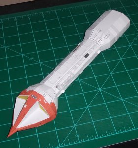
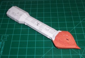
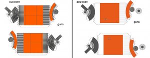
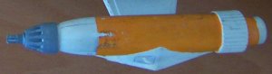
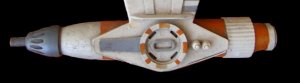
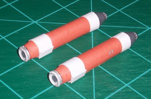
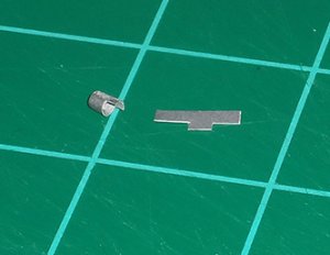
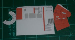
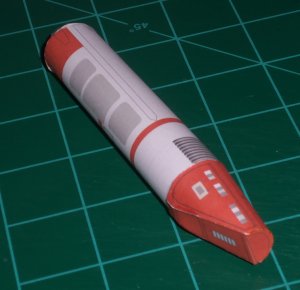
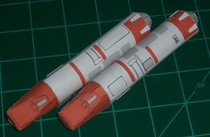
One goof I made you can see in picture i_5. Look at the end and you’ll see a white area on the flat side toward the front. This should have been on the panel section toward the rear!:sour: I switched the file around and printed out new panels and glued them over the old ones. You can see the corrected look in the last picture. You can also see the “H” shaped parts I made that were missing. On these parts I have a few areas where the glue and watercolor pencils I’m using made the ink run a little. I don’t like it but it does kind of look like weathering, which the studio model has in spades! So to get over that I’m telling myself that this ship is mostly new out of the factory and is just starting to show some space mileage.:D
 

Attachments

  • i_6.JPG
    i_6.JPG
    146.5 KB · Views: 11
  • i_7.JPG
    i_7.JPG
    321.3 KB · Views: 12
  • i_8.JPG
    i_8.JPG
    252.7 KB · Views: 12
  • i_9.JPG
    i_9.JPG
    524 KB · Views: 13