Simple wiring question

Grotto

New Member
Jun 29, 2006
39
0
6
66
Toronto
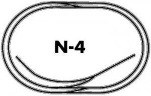
When using atlas terminal connectors to the common track, do you need another one on the other side that would feed back to the transformer. I am using the N4 atlas layout but it is not clear to me how to wire.

Secondly the N4 layout has 5 sections but it claims that it can be controlled by one selector(215) and I am not sure how this would work.
Thanks.
 
Hi Grotto,:wave:
For electrical current to flow, it must have a complete circuit. Current leaves a post on the
transformer, through a wire connected to one side of the track (terminal joiner), travels through the track
to the loco wheels, through the wheels to the pickups on that side, through the motor,
through the other side pickups to the other side wheels, back through the track to a
terminal joiner, and back to the other post on the transformer.:)

The resistance of the motor provides the load which keeps the circuit breaker from
tripping. Any path which allows current to flow back to the transformer without
passing through any load is a "short circuit", and will cause an overload (excessive
current.) :curse:

If you have a true "common rail" layout you may need only one connection on one side
of the transformer. The connections to the other side of the tracks and the other side
of the transformer can be separated through selectors or switches, allowing isolation
of parts of the layout. You can even run two cabs with the common rail connected
to both power packs, with the selectors determining which cab runs which section.
These methods are detailed in the Atlas wiring book, very inexpensive at your LHS.

Sorry for the long-winded post. :wave:
 

jim currie

Active Member
Jun 29, 2003
1,383
0
36
arizona
Visit site
not knowing that track plan if you have a common rail it in theory it needs only 1 connection but in the practical world you should have several feeders on it.
 

ezdays

Out AZ way
Feb 3, 2003
6,339
0
36
Arizona
bigbluetrains.com
Just a word or so on terminology. A "transformer" is a device that will take one AC voltage and convert it to a different voltage. For example, a transformer may take household 115 VAC and convert it to a lower 12 VAC. Since you are into HO and N scale, you might want to refer to your power device as a "power supply" or a "power pack". It is a common misnomer to call a power pack a transformer, but it comes from Lionel which uses AC to power the engines. Power packs have more than one output, DC for rail power and low voltage AC for accessories. The DC is variable to control the speed of an engine, but can also be used to determine the brightness of a light. Since DC has polarity, (+ and -), a power pack allows your engine to change direction by changing the polarity.

And Cid is correct in that you need to connect both sides of the rails to the power pack to complete the circuit. I cannot find the N4 layout you mention, but as Jim says, you probably should run several "feeder" wires to different places along the track so that you don't rely on one connection and the track to carry the current necessary to run the train, even if you are using a "common rail" configuration. A poor connection anywhere along the track, say at a rail joiner will cause problems. If you decide you are going to want to run more than one train at a time, then you will need to sectionalize, or "block" your tracks using insulated rail joiners and you definately need separate connections to each block section.
 

Grotto

New Member
Jun 29, 2006
39
0
6
66
Toronto
Please forgive me if I seem thick as a brick, but I am just trying to get some basic rules so I can wire my first layout.

1. On each block of track where there is a +, there must always be a -. No exceptions?
y or n
2. When using the Atlas selector (215), the book says one selector will be enough, but there are 5 blocks on the N4 layout.
Can you run 5 blocks on 1 selector?
3. Do you need to put 2 insulated conectors between block PLUS between crossovers?

The book claims that only 3 packages of terminal connectors (6 pcs) are required for the project, but it is starting to look like the book was wrong about that.
 
:) In the original post you mentioned the "common track." This means that one side of all the track sections or blocks is common, connected together, also called "common rail." Disregarding any voltage drop or poor connection issues with rail joiners, etc., this means that only ONE feeder is required from the common side of the Power Pack to the common side of the track. More feeds aid only with power loss issues, as decribed above by Jim and Don. Only the other side of the track requires gaps or insulated rail joiners. I think you only have about 60" of track from the transformer to any one point on the rails.
I don't see that one selector would do the trick, unless groups of isolated blocks are connected together as one. There should be some indication of how to wire this layout wherever you got it from, or it should be included in one of Atlas' wiring books. Did you ask Atlas? They are very responsive.
 

Attachments

  • 11004.jpg
    11004.jpg
    16.7 KB · Views: 215

jim currie

Active Member
Jun 29, 2003
1,383
0
36
arizona
Visit site
1. Y
2.each block should have a switch on the hot side.
3. 1 if using a common rail ,2 if not,depending on the track maker(think Atlas is one) crossovers are insulated
 

Russ Bellinis

Active Member
Feb 13, 2003
4,501
0
36
78
Lakewood, Ca.
Visit site
I don't know how you plan to run on this layout. If you plan on being able to run one train on the outside of the layout in one direction and a second train on the inside track in the opposite direction, then you will have to insulate both rails at both crossover tracks. In addition, only one rail can be the "common rail", the other three rails need to be insulated. When I mention one rail and the other three, I'm talking about the four rails on the two mainlines. The two spur tracks don't count. Also you have a trailing point and a facing point spur. If you don't fit a sceond crossover track in the bottom area of the layout in the drawing, the only way you will be able to get the locomotive behind a car to push it into the facing point turnout is to back 1/2 way around the layout.
 

Grotto

New Member
Jun 29, 2006
39
0
6
66
Toronto
The folk at atlas came through with an answer 4 days after my inquiry, which I consider quite good. Here is their response.

Grotto,

I believe that you discovered an error in our parts list for layout N-4. Thank you for bringing it to our attention. We will be starting to update Book #6 in the next few months and will correct the error at that time.

Since Atlas last printed Book #6, we have changed our recommendations for DCC wiring. Atlas no longer suggests having the program track a part of the layout. The [program track should not connect to any of your layout trackage and need not even be mounted on your layout bench work. Hence, you don’t need the double-insulated rail joiners that isolate Block #5. However, if you want the two sidings to be a separate block, add ONE (in the non-common rail) insulated joiner between turnouts #5 and #6 and also add a terminal joiner to the non-common rail that you isolated.
*** ******
Atlas Model Railroad Co., Inc. and Atlas O, LLC
378 Florence Ave.
Hillside, NJ 07205
USA
(908) 687-9590
*******@AtlasO.com