Roof Problem

Woodie

Active Member
Mar 23, 2001
2,093
0
36
Northern Rivers NSW Australia
Guys,

Hope you can provide me with some nifty ideas here.

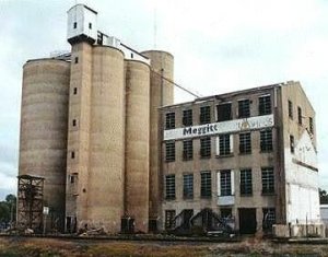
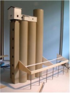
My latest project is a wheat silo, and loading dock. But I've got a bit of a problem with the roof. (pic below).

The cylinders (silos) are 255mm in diameter, and the roof of the loading dock is at 65 degrees from the perpendicular. (20 degree slope).

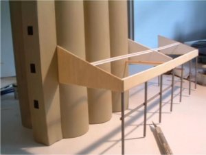
I need to cut some pieces that will fit slugly up into the silo cylinders, however, the cut out piece will not be semi circular, due to the angle of incidence with the cylinders. (they'll need to be cut in a semi "elipse".)

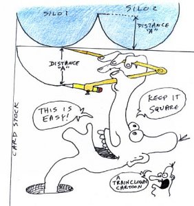
Truoble is, I've no idea (other than hit 'n' miss) how to get a good cut and fit for it.

I'm going to use corrugated iron (not real stuff), and its actually metal (aluminium), so I really need it to be very accurate. One slip and the whole sheet is wasted really.

Any ideas? If I have some 3D modeling software etc, I could do it, and print off a template, and use that, but I don't have the software.

I've thought of using some very thin card, hit 'n' miss cutting to get it right, but I'm sure there's an easy way of juggling "something somehow" to get the curve I need.

Any help is really appreciated.

Thanks.
 

Arlaghan

Member
Sep 9, 2003
658
0
16
50
S. FL
Woodie, short of getting all mathematical on you, here's a suggestion for you:

Try the hit-n-miss method, but get a rough shape. Then file it down and test fit as you do so constantly checking the contour against one of the tubes. Eventually you will get it, then you can trace it onto the other areas of the roof to get the rest of the tubes cut out.

Or, if you want to try the mathematical method (it's not so complicated actually) Create a document in a graphics program that draws out the circle (to scale) of the tubes looking straight down. Then, using a little trigonometry (ok, so it gets a little tough here) calculate the projected length given your angle. The resulting number is how much you should stretch your perfect circle so that you get the elipse.

If you are interested, here's the formula you would use:

x = d / (cos(a))

where:
d = the diameter of a tube
a = your angle
x = the resulting stretch (the long dimension of your elipse)

example: (EDIT - duh, I just saw you put the values, let me change my example to use your numbers. Note: 65 degrees from the perpendicular is not 20 degree slope, it's 25 degrees. I wasn't sure which to use, so I used 20. The cosine of 25 is 0.9063, if you want to substitute that instead)

if your tube measures 255mm in diameter and the pitch of your roof is 20 degrees, you would get:

x = 255mm / (cos 20)
x = 271mm

Keeping the shorter dimension at 255mm you would stretch your circle to 271mm and print this out. This will serve as a template that you can cut into your roof to shape the contour. I recommend you leave a little bit of material and file it down to get a perfect fit.

Ok, sorry for all that!
Been a while since I've gotten all mathematical! :eek:ops: :D :) :rolleyes: :p
 

Woodie

Active Member
Mar 23, 2001
2,093
0
36
Northern Rivers NSW Australia
Originally posted by Arlaghan

Note: 65 degrees from the perpendicular is not 20 degree slope, it's 25 degrees. I wasn't sure which to use, so I used 20.

Arlaghan,

You're brilliant. :thumb: :D :cool:

I'll see what sort of drawing type software I've got. I know you can "stretch" circles in MS Paintbrush, but I don't think it has any sort of scale to work with. But I'll look around.

And you are correct. My mistake.... thinking 45 degrees is a right angle!! sheesh!! :eek:ops: Then added it all up wrong anyway.... double :eek:ops: :eek:ops:

The roof is at 20 degrees slope from level, which makes the angle at the intersection of the cylinder 70 degrees.

angle a + angle b + angle c = 180
angle a = 20, angle b = 90
20 + 90 + angle c = 180
angle c = 70

I have tried freehand with some thin card, using the base of the cylinders, and it's not a bad fit straight off. But I'll see what I can do with some drawing software somehow first.

Much appreciated for your effort.

Thanks. :thumb:
 

scottg28

New Member
Nov 4, 2003
18
0
1
58
Illinois
Visit site
check this Link to another thread for a graph paper generator. If you download and install it then:
get a new sheet - Change Variant = Curved Patterns -> Ellipses
Enter 2.71 cm + 2.55cm for height and width
Select = Tangent (default is overlap)
You will now get a sheet with ellipses side by side in the appropriate size => print and cut 3 out for the pattern

I didn't try it, but you can easily change the values if the math is off or if it just doesn't quite fit

hope this helps

scott
 

Tileguy

Member
Apr 28, 2003
766
0
16
64
Northern Mn
Visit site
There is a tool available for doing exactly what you are looking for.it is available at most any hardware store and is very inexpensive.
It is called a contour gauge.
it has a bunch of tiny wires in a clamp. you loosen the clamp,push the contour gage into the area and it will give you the exact shape you need.cut to fit and file where necessary.
 
F

Fred_M

Gee, a free trig lesson. What more could a man want from a forum. No wonder your buildings look so good, you use math and I use a pair of worn out scissors and lots of glue. :thumb: DASH
 

George D

Member
Aug 28, 2003
229
0
16
86
Yorktown, VA
Visit site
Originally posted by Tileguy
There is a tool available for doing exactly what you are looking for.it is available at most any hardware store and is very inexpensive.
It is called a contour gauge.
it has a bunch of tiny wires in a clamp. you loosen the clamp,push the contour gage into the area and it will give you the exact shape you need.cut to fit and file where necessary.

A good simple solution. I opened my CAD program and saw it wouldn't be too hard to design a roof template, then I saw your suggestion to use a contour gauge and it blew my idea right off the board.

George
 

Woodie

Active Member
Mar 23, 2001
2,093
0
36
Northern Rivers NSW Australia
Thanks guys for all of that. Well worth it. I'll give it a bash in the next few days, and post the results.

If it is a bit bodgey, then I've still got to put some flashing around the edges where the roof abuts the cylinders anyway.

That's gunna be a thought, as to what to use for that, and its curved, with an odd angle, and hence, will either need to buckle or stretch at the edges of the flashing. hmmmmm..... thinking!!
 
P

philip

"aluminum foil" flashing ?

Woodie: Flash it in one flash at a time. By the way the structure looks nice!

philip:thumb:
 

60103

Pooh Bah
Mar 25, 2002
4,754
0
36
Brampton, Ontario, Canada
Visit site
2 suggestions

Woodie:
1) cut a slot in the silos to match the angle of the roof and sllide the whole sheet in.
2) cut a block of wood to match the angle of the roof, sandwich the roof material in between and drill holes the size and spacing of the silos through the whole sandwich.
I'd go for the trig solution myself, but I can't even cut a round hole, let alone an ellipse.
 

TrainClown

Member
Apr 17, 2003
861
0
16
66
Saskatchewan, Canada
Visit site
Just ask a Canadian

Hi Woodie

We have exactly the same problem when making log cabins and the solution has been around for years. The way it's done is with a compass, but you don't use it to draw circles with.

Best way is to make a templet on card first, then mark out your tin.

Place a bit of card on the roof so it lays right against the silos. Judge the distance from the most inner point, in the V between the silos, to the edge of the cardbord. Make your compass this same distance. Now keeping the compass point and pencile point square with the edge of the card is the hardest part of the next bit. Put the point of the compass at the edge of the silos and the pencile tip on the card. Now trace the compass point around the silo, keeping it square, and draw a pencil line on the card at the coresponding spot. You will draw a pefect copy of the shape.

Carpenters do this when they install moldings around the corners of cielings as well. This is also how to transfer the shape of a tricky floor tile.

Leave the mathmatics to the mathmatitions.

TrainClown
 

TrainClown

Member
Apr 17, 2003
861
0
16
66
Saskatchewan, Canada
Visit site
I'll Draw what I mean

Just think that the compass is straight up and down and not laying down like this one looks. Distance "A" would be the farthest distance the pattern has to duplicate.

Hope this helps.
 

Attachments

  • woodie's.jpg
    woodie's.jpg
    42.8 KB · Views: 100

Woodie

Active Member
Mar 23, 2001
2,093
0
36
Northern Rivers NSW Australia
How embarrasment!!! oooppppsss.... :eek:ops: :eek:ops: :eek:ops: :eek:ops:

And no one really picked it up!!!

The cylinders are just 55mm in diameter. Not 255mm. I can't even read a ruler properly!! Measured the bloody thing starting at 20cm on the ruler and went "yep" 255mm. That's more than 12 inches!!! in HO scale???

**runs off and gets big stick and beats oneself around head**


:eek:ops: :eek:ops: :eek:ops:
 

Arlaghan

Member
Sep 9, 2003
658
0
16
50
S. FL
LOL! Actually I did catch it, but I made the mistake of assuming you meant 25.5mm :eek:ops:

In that case, your stretch would be roughly: ~59mm

Interesting, isn't it? That 20 degree slope only makes a difference of 4mm? But I guess 4mm is significant when you remember that it is a GAP that needs to be compensated.
 

MasonJar

It's not rocket surgery
Oct 31, 2002
5,362
0
36
Ottawa, Canada
Visit site
Originally posted by Woodie

And no one really picked it up!!!

... 255mm. That's more than 12 inches!!! in HO scale???

**runs off and gets big stick and beats oneself around head**


:eek:ops: :eek:ops: :eek:ops:

Sorry, Woodie, but you'll have to keep going... 255 mm is about 10 inches. 305mm = 12 inches.

Didn't want to be accused of missing anything, especially if you decide to use the big stick on someone else's noggin... ;) :D


Andrew