Rhino 3D Tips, Questions and Answers

cgutzmer

Well-Known Member
Hello!
I have been chatting with Zathros quite a bit about Rhino - His knowledge base on the subject is outstanding and has been a HUGE help with only a few simple tips. I am going to ask a couple questions he already answered by email figuring he can post those up and maybe include a couple screenshots then we can move on to some other questions. Anyone feel free to chime in with specific questions, tips and such as well! As it relates to card modeling of course since thats why we are here :)

Thanks!


Question 1 (multipart): What can Rhino do in the grand scheme of things? Just the 3D design? Can I do the actual paint job of the final model? Can I flatten it so its buildable? After its painted (final livery) can that be rendered into the 3d view as a sample of what it will look like built?

Question 2: Can you give me a quick overview on how to join up parts and unroll them?

Thanks!
Chris
 
Z

Zathros

Chris, great title! I couldn't have thought of a better one. There are many others we know of who use Rhino, here, and at Papermodelers.com, with the input of just a small percentage of these persons, we should be able to get a great reference section going. Not too small though!!

The first question is answered by one word, YES!

The 2nd question, YES! I will put a sample together with some screen shots to show others what we have talked about.

I would love it if some of the members, such as Goodduck, Goldenbear, Gil to name a few, three who have helped me out quit a bit and Aaron, who goes by Murphyaa (at Oddball productions who bangs out models at an incredible rate ), and a couple of others, joined in on this. There are may ways to do things in Rhino that can lead to the same result, if not similar. Sometimes it is a matter of what you are comfortable with. Rhino also does well in exporting to many other formats, a lot in fact. It works extremely well with Photoshop and even Paint. Actually, since you can export in .jpeg, you can work your final print in almost anything.

Rhino will also print in exact scale. If you wanted to scale something up to human size, Rhino will allow you to print in individual small sheets that you can tape together to form a large model, or pattern, let say for for instance, a sailboat. More to come.....?

How many hear are using Rhino and wish to see such a tutorial?
 
Z

Zathros

Any other takers? I wouldn't want to do this if there is not much interest. It is time extremely time consuming!! Any other takers? This program can be downloaded for free and use 30 times, I believe, then the save feature is disabled, but works otherwise. Not sure if the print feature is disabled?
 

cgutzmer

Well-Known Member
I think start simpler than something full blown.... after some questions and answers it might be easier to rework that into a tutorial :)
 
Z

Zathros

I was just offered compensation to do the same thing. I told this person, when you have a month or some of 2 hrs. a night into Rhino, maybe we can talk. I think the first thing someone should do is familiarize themselves with the control layout. First thing is to enable the Snap Toolbar. This is in the Index under "Help". Quickly, it is to the right of the tiny Red Car (this will seem strange to someone who doesn't have Rhino). about 2 spaces. It looks like a circle with a dog and a line going 90 degrees to the left till it hits the circle.. Right clicking this will enable the Snap Toolbar. This toolbar, and familiarization is essential for being to locate yourself inside 3 dimensional space.

I think if someone posts a screen shot of what they are trying to do, then I can show them, or, a diagram with what they are trying to do. Just don't post a picture of an airplane,. please.

The other command is placing background Bitmaps. This allows you to trace parts. Keep the images small. They can be .jpg, ..bmp, just about anything. That control is under "View".

Understanding where the basic buttons are is most important. Also, there are many tutorials online that should be investigated, and many posts at Papermodelers.com. If you go into a section there called Zathros's Projects (join the forum if you cannot see the pictures, I am a member there also), you will see many methods explained and pictures with the results. Pick ONE model you want to do, preferably something that you have the formers for. This is because jumping around will not be efficient.

Make a line, or curve, and see what you can do with it, to familiarize yourself. Rhno is very intuitive, but takes much dedication to use. There is no difference between a paper model and some more tangible. Rhino is a true CAD program. It is not a drawing programmed to be something more.

Former a square, then form a sphere and use on to cut into the other, exploration is the first necessary step. :)
 

cgutzmer

Well-Known Member
Sorry - been really busy at work and havent gotten to check in lately.

If you were offered compensation then you better get on it! At least if its something you are interested in :)

Are you going to post up those quick tips you gave me then move on from there? At least getting the very basics out there would be good.

I do suggest to anyone at least go through the first 50 pages of the tutorial with Rhino to familiarize yourself with the app a bit :)
Chris
 
Z

Zathros

No, those were for you. There could have been more but that's neither here or there. Pick something you would like to design, as I posted earlier. Make it simple. Find a drawing that has formers. I don't want to make models off of 3 way drawings as they tend to be grossly inaccurate. It can be a boat. If you can't find anything, I will design a small sharpie style boat, of my own design, to start with. I will only make one or two things, then you, and anyone else reading, will have to learn just the way everyone else had to. I will try and help with some questions, but I am not a pro by any way shape or form. I have not seen any designers that have expressed interests in divulging their own secrets. I have some of my own that I keep. I will help with the basic stuff though.

I am extremely busy this time of the year. This thread could die, and fast, if the interest is not kept up. My last suggestion was that you find something you want to design, something simple. Also, imagine that it is best to work in 1/2 models on symmetrical objects. I think a Sharpie boat is a great way to start. It is simple and requires little, and can be modified highly to make a quite nice model. You want to do a Sharpie?
 

cgutzmer

Well-Known Member
sure - that sounds great! You can draw up a little boat. The basics are all I am after. I imagine after that it becomes more a matter of personal preferences and tastes!
Thanks
Chris
 
Z

Zathros

sure - that sounds great! You can draw up a little boat. The basics are all I am after. I imagine after that it becomes more a matter of personal preferences and tastes!
Thanks
Chris

Great, I'll set up something tomorrow. Not sure how to do this because I don't think I can attach Rhino files. If I have to do screen shots, it will take a lot of wording. We'll play it out, some technique should develop. :)
 
Z

Zathros

Here is a picture (Render) of the Sharpie, Alliance. It is a generic boat of my own design. It will be the basis of the tutorial on this thread. I have to experiment with how to do this, but it's a coming! The Hull is done. I just have to make a series of screen shots with the explanations of what each picture represents.:)
 

Attachments

  • Aliance 1.jpg
    Aliance 1.jpg
    64.9 KB · Views: 19
  • Alliance 2.jpg
    Alliance 2.jpg
    44.9 KB · Views: 12

cgutzmer

Well-Known Member
very cool! And a rhino generated texture to boot! Let me know if I can help post anything up - still been familiarizing myself with the interface even though time has been really limited cause of a big project and being on call darn it all :) I would rather be modeling!
Thanks
Chris
 
Z

Zathros

Well, I just realized my first mistake. I built the model, thinking I would go back and offer explanations, which is ridiculous, when I could have done screen grabs of each step, with minimal verbiage. Also, I don't like the lines of that boat. So I am starting over, which is actually quite simple. The name Alliance still sounds good.

To anyone following this. Create a Folder with the name of the boat, in that folder, create another folder called textures, and one more called Renders. I got the texture for that mode by tying wood texture in Google and it comes up with a billion samples. Make sure the one you chose does not have any writing on it. 250 x 330 , anywhere around that size will be fine for what we are doing.
 

Alcides

Member
Question 1 (multipart): What can Rhino do in the grand scheme of things? Just the 3D design? Can I do the actual paint job of the final model? Can I flatten it so its buildable? After its painted (final livery) can that be rendered into the 3d view as a sample of what it will look like built?
Thanks!
Chris

Hi Chris

Well, I'm not a designer , just one model, but I've been working for a long time with Rhino a several designs what I think to complete some day.

I can separate the stages of design in the following phases and where Rhino can help in my knowledge:

1) Research and get a good 3d view: well time, internet books, no Rhino for this one, it's sometimes the hardest part :rolleyes:
2) Trace 3d view and pane line: You can't work well with a bitmap, a good starting point is trace with a vectoring software, but you can do it directly in Rhino. It's better and you don't have to work with another software. More you can do the pane line and markings.
3) 3d Design: Of course here's where Rhino shines. The design of surfaces for later unroll them is very easy.
4) Pane-line & marks: you have the ability to project lines on Rhino over the surfaces, so you can avoid a latter headache working directly in Rhino.
When you unfold the surfaces you can get the marks & pane line ok.
5) Unfold: You can unroll all your surfaces with Rhino with then pane lines & marks, of course you've to take care of design just surfaces doubled in one direction.
6) Page design: I found easy to do a general arrangement of all unfold pieces before to transfer it to a vector program to work in colors.
7) Coloring: I know you can do something in Rhino, but I do it on Corel.
8) Instructions: You can do diagrams directly with renders in Rhino as several models from Polish shows.

I can't promise nothing but maybe I can put together some examples I've from some of this steps.

Regards
Alcides
 

cgutzmer

Well-Known Member
cool - thanks! I think a lot of this will come out in what Zathros has planned too :) sounds like it can do quite a lot and might be worth that rather hefty pricetag... ;)
Chris
 
Z

Zathros

I think the Backround Bitmap, and Picture Frame Options work really well in Rhino. The pictures can be jpegs, I don't know why they called it that, and in PictureFrame, the pictures can be locked. The projecting of lines and such is excellent. We will get to that but this is really a ground up tutorial. The idea being to help someone who has no experience in CAD. The features you mentioned will be a little down the road, but not too far. As far as Corel, or Photoshop, that won't be covered in this, but if you wish to start a thread showing how you do this, you are more than welcome to! I attached a sample of what can be done with the PictuureFrame option. This is not necessary for creating your own work though.

I am really happy you joined in Alcides. Very Happy! :)

attachment.php
 
Z

Zathros

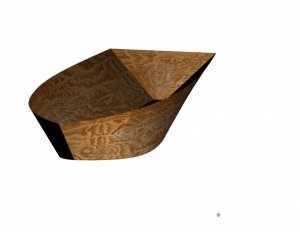
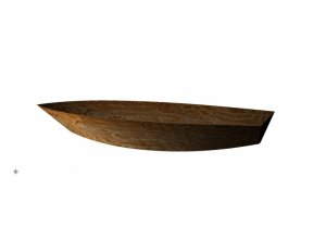
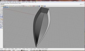
This is the text of how to build the attached boat. The pictures that go with the text are in the following post.

Open Rhino, Select "Small Objects-Inches, click "Open"

Double Click Top to Enlarge the Top Viewing Pane

On the Upper ToolBar, on the Second Icon to the right of the little Red Car, right click the button to enable the object snap toolbar by holding cursor over first icon from drop down menu and clicking "Show Object Snap Toolbar"

A ToolBar will appear on the Bottom. This Toolbar should always be present.

Underneath you will see other words, make sure the word "Ortho" is NOT highlighted ( Ortho makes it easy for you to make straight lines, later on that)

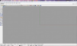
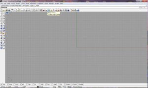
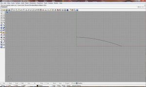
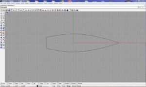
Your screen should look like the picture named "Start" At anytime you can use the "White Hand to move the whole Scene around. it is not moving the part, just your relative view.


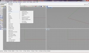
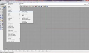
Do the following in this order Click/Curve/Free Form/Control Points/Click Points

Type, 5,0 (zero,zero, not the letter "O")
Type 3,.750 enter
type 1,1 enter
type 0,1 enter, then Right Click to finish

This can be done with out numbers. You can just eyeball where you want the control points to be. I am doing it this way because of the other steps I want to show you.

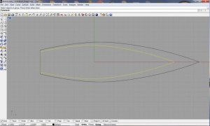
Your screen should look like ClipBoard 5.

Click the curve one time to highlight it.

Go to the bottom of the screen and click "ORTHO".

On top of screen, click "Transform", on the slide down, click "Mirror"

Click the bottom tool bar where it says Enable (if it says Disable, it already is Enabled, this toggles this toolbar on and off). Check the box to the extreme left that says end. Make sure Otho is still highlighted.

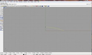
Clipboard 4 shows the cursor "snapped" to the end of the curve. This is what snap does. Click once, and slide the cursor down and you will see the mirrored part appear on the left. Click once to end that step.

It will only go parallel, or perpendicular because Ortho is on.

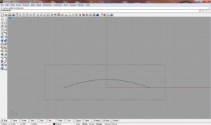
Just slide the cursor down and it will look like clipboard 6

Click somewhere away from the lines and drag the mouse. This creates a box that can be used for selection. Create a box, and select the two curves.

Both curves should be highlighted yellow, go to the right ad click "Join", it looks like two puzzle pieces. This will join the two curves together.(See clipboard 8).

At this point, I will tell you what to do, reference above commands if you get lost.

Transform/Mirror/,snap to end of curve/bring other end of mirrored part to other end of original curve. Click to finish.

Remember, the point of this is to learn commands, not the fastest way to make a simple boat.

Create a box- Go to "Solid", slide down, slide to "Corner to Corner" Click once.

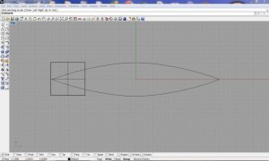
Place cursor in open area and draw a box 2 by 2 inches and type in 2 for the next dimension.

Position the box so that it looks like clipboard 9. We are chopping off 2 inches. Make sure NOTHING is highlighted, just click an open area, or press ESC.

Go to the right of the screen and find the button that has a "white rectangle, and a triangle going into it" (not the broken rectangle) Click it once, this is the "Split Command, in the Dialog box, it will say "Select Objects to Split, click each Curve that intersects the box. Press "Enter when done, or right Mouse key. The Dialogue box asks for a cutting object, select the box, Press Enter, or right mouse key. Select the Box, and the two curve pieces you just cut but drawing a box around them, they should be highlighted, go to EDIT, and find Delete and press it (Up Top next to File).

In the EDIT commands, you will also find the Join, Explode, etc.


Next, Curve/Line/Single Line Snap the lines to the ends you just cut off. That will be the transom. See Clipboard 10.

Draw a box around the whole drawing to select it. When it is completely highlighted, go to "Transform/Copy, click on the middle of the transom and drag to the right around 1/4 inch.

Now, put ORTHO on and drag the Yellow model so that both transoms line up

Go to "Transform/Scale/Scale 3-D, slide the line to ),) (where the Red and Green line meet) click and drag back the bow 1.25 inches, which is 5 small blocks. Click when finished. Refer to Clipboard-11

Go to EDIT/Groups/Group, carefully select the smaller pieces one at a time, If you select the wrong part, Hold Ctrl Down and click the wrong part again to deselect it. Press Enter when done.

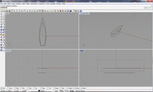
Double click Top to go back to 4 pane view.

Select(Highlight) the smaller drawing and underneath in the Front view, slide it down 1 inch.

At this time, in the Top View, select the whole unit with a box, and go to "Transform/Rotate, put the cursor right over 0,0 and rotate so the box is pointing up. Drag the line to the right, a circle will appear, and just drag the bow up. This will orient the craft correctly in relation to the windows.

Now comes the "Subjective" part.

In the Right (Lower Right) Pane, select the top line you see with a selection box, like you selected above. See Clipboard 12, when you are done in the Pane above that (Perspective, you will see the top shape selected).

Click "Ortho" off

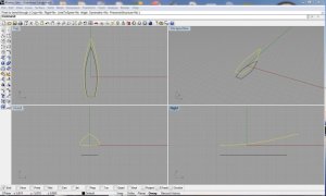
Go to Transform/Bend, Snap Cursor to Transom end go past the bow an inch and drag upwards to make the curve you wish. Se Clipboard-13.

If you make a mistake, the curved arrow next to the white hand wll take you back on step. When satisfied:

Transform/Rotate snap to the transom and Rotate down till the box is around 1.5 box's (1.375") up from the transom. See clipboard 14.

Now select the small shape with a box

Transform/Bend, but this time start in the middle of the lower shape and bring it up slightly (make it look like a boat!)do the same for the rear. Ref. clipboard-15.

Go to Curve/Line/Single Line...Snap one end of the line to the top of the bow, and the other to the Bottom

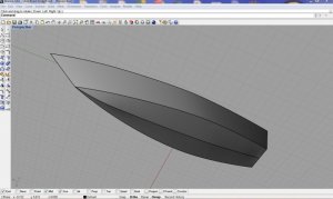
Double Click the Top Pane to Enlarge it. Go to "Surface/Sweep 2 Rails. Select the small curve on right hand side, then the large curve on the right hand side, then the line connecting the bow points, as the profile curve (it does this automatically, just select in the order I told you) Then press Enter, or you Right mouse Key. Click O.K. in the Dialogue box that appears. Do the same thing for the other side. If you feel brave, you can also Mirror it. I wouldn't though, not for this kind of model.

Double click "Top" to get back to the 4 window view. To the right of the "White Hand" is a Global looking Icon, this allows you to rotate the view. Do this in the Perspective box so you can look at the model.

It is easier to do the transom surface in the Perspective view. Double click it. With the rotate button, position the transom so you can see it easily. If it is too small, in large it with the magnifying glass button with the +- in it. Click the button, dragging up make it bigger, down, smaller, use the white hand to position the drawing where you want it.

Surface/Sweep 2 Rails, select the sides and the top line and click O.K. and the surface will form, just like you did on the sides.

A flat bottomed boat, how boring. Let's add a chine.

Double click Top, Enlarge the picture big enough (huge, using the Magnifying glass with +- in it)) so that you can see the line in the middle of the transom. On the Snap ToolBar, Check the Box that has "Mid" written next to it. Running your cursor on what would be the bottom of the transom, you will notice that at the "Midway" point, the cursor locks, at this point, click, to start your line, put ORTHO on. Now, Reduce the size of our picture so you can see the whole boat. Ref. Clipboard-17

Go straight up towards the bottom of the boat till you get to the bow, make around 10 points. Double click Top to get back to 4 way view.

Click the line you just made to highlight it. Turn of the Snap toolbar by pressing Disable. Double click the right window to enlarge it.

Go to EDIT/"Control Points/"Control Points On"/. Ref Clipboard 18.

Turn Ortho On. You are going to pull each dot down to form a smooth line slightly lower than the sides of the boat. Ref. Clipboard 19. That's good enough for me. More chines could be added but not really fitting for this boat.

Edit/ControlPoints/ControlPoints Off.

Now if you go to the Perspective screen, and roll the boat around, you should see your gentle center line for your chine. Just in case anyone hasn't noticed, this can be a tiny sharpie, or the beginning of a fuselage for an amphibious boat? I wonder where we will end up at!

Turn the Snap Toolbar back on.

Curve/Line/Single Line...Snap a line from the bottom Mid point of the transom to the bottom end of the side panels (1 each side)

This is one of those things that is easily done in the Perspective Window.

Surface/Sweep 2 Rails..Select the Center (Keel) line, the bottom of the side panel and the line you just made from the mid point, as your profile curve, click O.K. in the Dialog box and the chine will be made. Remember that when you select Run 2 Rails, you just select the lines, if you look at the line where you type entries, you will see the questions being ask, so try and keep track as to what's going on. Repeat to make the other chine. Right click the perspective Windows box (On the word "Perspective" to get Render options. Ref. Clipboard-20 to see where I left off.

Decking, chairs, who knows what will be next?
 

Attachments

  • Clipboard-20.jpg
    Clipboard-20.jpg
    92.7 KB · Views: 17
  • Start .jpg
    Start .jpg
    83.8 KB · Views: 73
  • TopView.jpg
    TopView.jpg
    93.7 KB · Views: 68
Z

Zathros

Reference pictures.
 

Attachments

  • Clipboard-1.jpg
    Clipboard-1.jpg
    109.1 KB · Views: 20
  • Clipboard-2.jpg
    Clipboard-2.jpg
    85.7 KB · Views: 23
  • Clipboard-4.jpg
    Clipboard-4.jpg
    92.6 KB · Views: 17
  • Clipboard-5.jpg
    Clipboard-5.jpg
    85.6 KB · Views: 66
  • Clipboard-6.jpg
    Clipboard-6.jpg
    89.1 KB · Views: 51
  • Clipboard-7.jpg
    Clipboard-7.jpg
    94.2 KB · Views: 68
Z

Zathros

Reference pictures continued
 

Attachments

  • Clipboard-8.jpg
    Clipboard-8.jpg
    72.6 KB · Views: 15
  • Clipboard-9.jpg
    Clipboard-9.jpg
    87.5 KB · Views: 12
  • Clipboard-10.jpg
    Clipboard-10.jpg
    86.1 KB · Views: 16
  • Clipboard-11.jpg
    Clipboard-11.jpg
    84.5 KB · Views: 77
  • Clipboard-12.jpg
    Clipboard-12.jpg
    104.5 KB · Views: 36
  • Clipboard-13.jpg
    Clipboard-13.jpg
    110.2 KB · Views: 16
Top