Pwr Supply, CDU, Diode Matrix, Switch Machines

racedirector

New Member
Apr 4, 2004
48
0
6
63
Oz-stralia
australianspeedway.com
Hi all

I am looking for a little help in getting the above combo right. I think I have sussed out the order of things but am confused by the power requirements and the details of how it all fits together. :confused:

(1) Pwr Supply -> (2) CDU -> (3) Diode Matrix -> (4) Atlas Switch Machines.

Given the combo above...

Item 1: Scratchbuilt power supply. Which transformer would be better?

1. 24V 3A 72VA Single Winding
2. 9V - 24V 5A 60VA Multi-Tap
3. 12V - 30V 6A 100VA Muli-Tap
4. 12V - 30V 8A 120VA Multi-Tap

Would it be sensible to power the CDU AND the Diode Matrix from this one power supply?

Item 2: CDU
Power source: 16V to 24V AC. Correct?
Capacitor: 4700mf for up to 6 machines. Yes?

Item 3: Diode Matrix
Power source: 16V to 18v DC. Correct?

Item 4: Atlas Switch Machine
Power Source: 16V to 24V AC. Correct?

What I want to do:

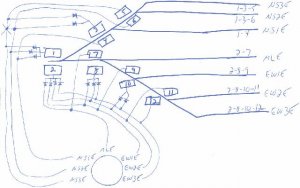
My hidden staging will consist of a mainline with 3 tracks either side, double ended, making a total of 7 tracks. A total of 12 turnouts will be involved, 6 either end. A rotary switch will select the track (NS1, NS2, NS3, EW1, EW2, EW3) and a pushbutton will activate the switches to get that route out onto the mainline. The CDU will provide the oomph to activate the required switch machines and the diode matrix will activate all of the switches for the selected route. This could be up to 6 switches at a time (both ends of staging).

That's all for the brain dump at this point. If anyone can shed some light on the questions above and maybe even the interconnections I would really appreciate it :thumb:

Cheers
Bruce
 

60103

Pooh Bah
Mar 25, 2002
4,754
0
36
Brampton, Ontario, Canada
Visit site
Bruce:
One power supply. (see my reply to your other post)
The AC goes into the CDU. The output from the CDU is a high powered burst of DC. This goes via your pushbutton, any selector switch and the diode matrix to the switch machine.
Do you need an explanation of the "diode matrix"?
I think you should control each end of your yard separately. That way, you can move a train in while moving another out from a different track.requires the CDU or else a big power supply and a rectifier.
 

racedirector

New Member
Apr 4, 2004
48
0
6
63
Oz-stralia
australianspeedway.com
Thanks again David

Silly me didn't realise that it is DC coming out of the CDU. I think I will go either number 2 or number 3 transformer above.

I should be right with the diode matrix, there seems to be heaps of information around about them. Thanks for the offer though. Then again if I get stumped by one, I'll be back!

Cheers
Bruce
 

60103

Pooh Bah
Mar 25, 2002
4,754
0
36
Brampton, Ontario, Canada
Visit site
The diode matrix is a nice diagram to figure things out, but the actual wiring can be a bit cruder.
Assume you have one switch A and it leads to switch B on the straight side and C on the curved side. Your sidings are B1, B2, C3 and C4,
You wire the push buttons to the terminals on switch machines B and C.
The two terminals on B have diodes connected to them (pointed the same way) and the free ends are joined together. Same for C. The diodes from B are wired to the terminal on A that throws it straight. Diodes from C wired to the curved terminal.
When you push B1, the electricity flows to the terminal on B then through the diode to A. It doesn't flow to the other terminal on B because the second diode blocks it. From this building block, you can wire a whole yard.
The direction of the diodes has to be co-ordinated with the output of the CDU. I usually test it with a diode on the end of a wire as a probe, to see which way it works.
 

racedirector

New Member
Apr 4, 2004
48
0
6
63
Oz-stralia
australianspeedway.com
Ok, I admit I am wrong...I do not know what I am doing :)

Here is a drawing of one end of my staging and the associated panel I want to build.

A number of things to note. Each end of staging will be controllable independantly, as seen in the drawing with the rotary switches. Each route selected by the rotary switch will be activated by the pushbutton below it. The selected route will also be signified by a diode next to it as well as diodes on the track plan above.

In addition to each rotary switch, there is a pushbutton to set all mainline switches to normal. There is also a toggle switch to join both ends of staging together so either end will select a complete route (both ends at the same time)

I know I am being ambituous with this and (maybe) have the basic wiring figured out (not including that damn matrix, which I thought was a cool movie btw :)).

Would anyone be willing to assist me in figuring out the wiring for it?

Cheers
Bruce
 

Attachments

  • staging-panel.gif
    staging-panel.gif
    21 KB · Views: 118

shamus

Registered Member
Dec 17, 2000
3,489
0
36
87
UK
Why not build a simple control panel and have it wired for stud and probe contact for the point (Switch) motors. Probe lead is on the far right. The studs are just nuts & Bolts. Don't forget the CDU which will be needed along with 16 to 24volt AC transformer.
Shamus
panel.jpg


Gary Pfeil

Active Member
May 7, 2001
2,510
0
36
Boonton NJ
Visit site
Bruce, Here is a quick and dirty sketch (the only kind I do) of the matrix for your throat. What I do is # the coils which activate the routes, then list the coil #'s needed for a given route. You see these coil #'s in boxes on the drawing, and the coil #'s written above (some below) the tracks on the right side. Every coil that is used in more than one route needs diodes, one for each route. Then it is simply a matter of feeding the contact on the switch to the appropriate coils, thru diodes on those coils which need them. The diodes allow power to reach the coil, but not travel back down the other wires. Or else you'd be powering coils you didn't intend to. I hope I've done an adaquate job of describing it.

Gary
 

Attachments

  • p1010443jpg.jpg
    p1010443jpg.jpg
    43.4 KB · Views: 107

Gary Pfeil

Active Member
May 7, 2001
2,510
0
36
Boonton NJ
Visit site
BTW, if it were me, I'd do as Shamus suggests, and use stud/probe to throw turnouts. One contact for each route on the panel. This is why I'm able to use my 8 amp supply (rather than cdu, as we talked about on the other thread) without worrying about burning out coils due to sticking switches.

Gary
 

racedirector

New Member
Apr 4, 2004
48
0
6
63
Oz-stralia
australianspeedway.com
Thanks Guys

Gary
Those little confusing diodes were the ones. This way, that way - ahhhh! Your quick and dirty is just fine! (Mine would have been the same but the scanner isn't working at the mo)
]
Gary & Shamus
The stud & probe idea is a good one. At first I didn't see using for route setting vs setting individual switches. But now I have had some sleep it has all become clear!

I think I'll still use a CDU just for added protection. I have a 4 and a 6 yr old that would probably like playing with the probe when I'm not around! :)

Now, to tie all the rest of the fancy bits into it :)

Cheers
Bruce
 

jon-monon

Active Member
Aug 15, 2002
4,590
0
36
59
Cobblers Knob, IN
www.2guyzandsumtrains.com
Those little confusing diodes were the ones. This way, that way - ahhhh!

If the arrow points towards the more negative voltage, it will conduct. The stripe on the real diode corresponds to the stripe on the real diode. So, if you look at the stripe on the real thing as a "-" sign, that's how you wire it "on". Clear as mud LOL:D
 

racedirector

New Member
Apr 4, 2004
48
0
6
63
Oz-stralia
australianspeedway.com
Originally posted by jon-monon


If the arrow points towards the more negative voltage, it will conduct. The stripe on the real diode corresponds to the stripe on the real diode. So, if you look at the stripe on the real thing as a "-" sign, that's how you wire it "on". Clear as mud LOL:D
Aha! I see.......I think.....let me clear that mud away first! :D